Service Manual
DS 350 Modular
© PAT
Rev. - 12/18/00 // CSH.
190118_-.DOC
20
11
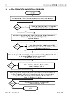
AREA DEFINITION INDICATION PROBLEM
Check proximity switch or activation stump or rail for physical damage.
START
Repair as necessary, check Link-Belt load
chart for correct switching point.
END
NO
YES
YES
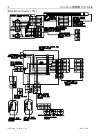
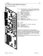
Measure signal from the proximity switch in the central unit between X1:16 and
X1:35 with the stricker in front of the switch and the LED in the switch is on.
voltage should be between 24 volts and the DI3 LED should be on.
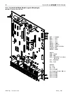
Refer to Drawing 1, 4, and 8.
Measure the proximity sensor supply voltage in the central unit between
terminals X1:33 (+24v) and X1:35 (ground).
Refer to Drawing 1.
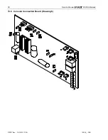
Main board defective. Replace main board.
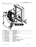
Refer to Drawing 4 in Section 12 and Replacement
Procedure 3 in Section 13.
NO
Correct?
Correct?
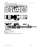
Measure the proximity sensor supply voltage at cable assembly (031-300-060-192)
4 socket plug between A (24v) and B (return).
Refer to Drawing 1 and 8.
Cable assembly defective. Replace cable.
Refer to Drawing 1 and 8.
NO
Correct?
YES
Proximity switch defective. Replace switch.
Refer to Drawing 1 and 8.
NO
Correct?
YES


