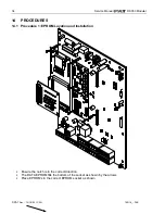
Service Manual
DS 350 Modular
© PAT
Rev. - 12/18/00 // CSH.
190118_-.DOC
36
14.3 Procedure 3: Angle Sensor Adjustment/Replacement
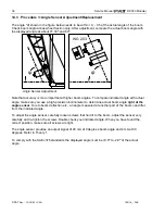
The angle "
φ
" shown in the figure below needs to be 0, - 0.5 of the actual angle of the boom.
Check boom angle at base/heel Section only. After adjustment, compare the actual boom angle with
the displayed angle at about 0
°
, 30
°
and 60
°
.
WG 203
φ
φ
Angle Sensor Adjustment.
Note that accuracy is more important at higher boom angles. To compare indicated angle with actual
angle, make sure you use a high-precision inclinometer to determine actual boom angle
right at the
angle sensor
. Due to boom deflection etc., an angle measured at another part of the boom can differ
from the indicated angle.
To adjust the angle sensor, carefully loosen screws that hold it to the boom, adjust the sensor very
carefully and re-tighten the screws. Double check your indicated angle. When you have found the
correct position, make sure all screws are tight.
The angle sensor provides an output signal of 20 mA at 0 degrees boom angle and 4 mA at 90
degrees. Refer to Theory 1.
To comply with the SAE J375 standards the displayed angle must be +0.0
°
to -2.0
°
of the actual
angle.

