background image

56

PA8500-VES System

System Manual | 2014

UK

CR8506-V 

|

 RT8506-V

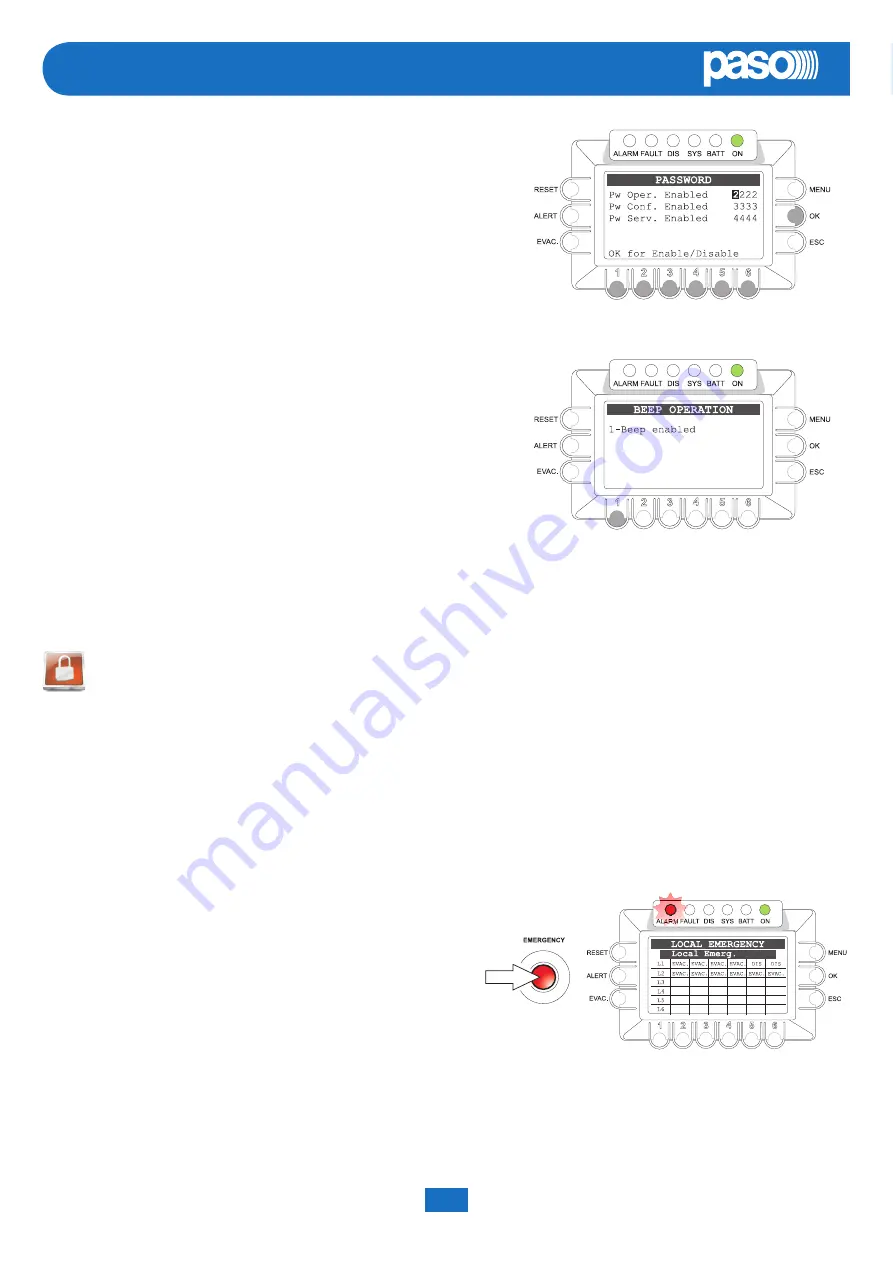
8.7   MANUAL EMERGENCY - < EMERGENCY > Menu

Following is a description of the procedure for managing emergencies manually by an authorised operator.

8.7.1   General information

The.manual.emergency.mode.is.accessible.at.all.times..Manual.emergencies.have.priority.over.any.pre-recorded.messages.being.broadcast.

and.that.were.activated.by.an.external.peripheral.unit.connected.to.the.“control.Inputs”.and.over.any.emergency.stations.able.to.broadcast.

messages.via.the.6.output.lines.of.the.controller.being.used..

8.7.2    Manual management of emergencies

As.explained.below,.thanks.to.its.dual-channel.operation,.the.CR8506-V.controller.enables.structured.management.of.alarm.messages,.of.

muting.of.the.messages.and.of.selection.of.the.zones..Following.is.a.list.of.operations.providing.a.brief.introduction.to.manual.emergencies.

A) SENDING OF AN EMERGENCY MESSAGE FROM A CONTROLLER

-.. Press. the.

EMERGENCY

. key. once.. The. key. will. light. up. steadily..

Activation.of.the.emergency.mode.will.also.be.shown.on.the.routers,.

stations.and.any.other.controllers.connected.to.the.controller.

-. Send.a.voice.message.(using.the.hand-held.microphone).or.an.alerting.

message.(

ALERT

.key).or.evacuation.message.(

EVAC

.key).to.all.zones..

The.display.will.show.the.type.of.message.being.broadcast.

N.B.:  Messages  sent  using  a  hand-held  microphone  have  absolute 

priority over pre-recorded evacuation and alert messages.

To.end.live.emergency.messages,.alert.messages.and/or.evacuation.messages,.press.the.

EMERGENCY

.key.again.

8.6.7 

PASSWORD


Setting the password

Panel. for. enabling,. disabling. and. customising. the. password. for. accessing. the.

system.service.levels.

•.. Use.the.+/-..knob.to.position.the.cursor.on.each.digit.of.the.password.to.be.

changed

•. Use.the.numerical.keys.(1-6).to.enter.the.new.password

•. Press.Ok.to.enable.or.disable.the.password.as.set.

Note: 

The display will show the new password programming that has been set.

8.6.8 

BEEP OPERATION


Management of the system “beep” 

Panel.for.enabling.and.disabling.the.system.“beep”.

•. Use.key.

1

.to.enable.or.disable.emission.of.the.acoustic.signal.

Nota: 

The display shows the status of the set programming.

Upon.completion,.press.ESC.to.return.to.the.CONFIGURATION.menu.

Summary of Contents for CR8506-V

Page 1: ...Cert EN 54 16 2008 n 0068 CPR 082 2013 CR8506 V VES Controller Voice Evacuation Systems PA8500 VES RT8506 V VES Router Instructions for use Version 1 3 ...

Page 2: ......

Page 3: ...2 6 1 INTRODUCTION 22 6 2 CREATING A NEW PROJECT FILE 22 6 3 OPENING AN EXISTING PROJECT 22 6 4 INSERTING THE CONTROLLERS 23 6 5 CONFIGURING THE CONTROLLER 23 7 MENU STRUCTURE 30 7 1 HOME functions Access to the Option Menus 30 8 USING THE SYSTEM 33 8 1 Initialising the system 34 8 2 MUSIC MENU 35 8 3 AUDIO SETTING MENU 37 8 4 INSPECTION MENU 40 8 5 OPERATOR MENU 48 8 6 CONFIGURATION MENU 52 8 7 M...

Page 4: ...ss are required The simplicity of the connections using Cat 5e SF UTP shielded cable between the various different management units amplifiers and emergency microphone stations makes sound broadcasting in complex buildings effective and inexpensive enabling the use of both centralised and or local equipment Each CR8506 V controller has provisions for managing 6 control lines to which the following...

Page 5: ... System Manual 2014 PA8500 VES System UK CR8506 V RT8506 V CR8506 V controllers and digital amplifiers of the PMD CR8506 V controller and RT8506 V PA8500 VES System featuring a mixed configuration ...

Page 6: ... PMB106 G PMG112 G R5 Balanced input for a microphone or outside source Terminal block for connecting a precedence contact R6 Input for external microphone R7 Input for connecting an external source of music R8 7 monitored digital inputs for control via external peripheral units R9 6 output lines for connection to amplifiers of the PMD range and or PA8506 V compact systems and or RT8506 V routers ...

Page 7: ... dedicated software Automatic management of the stand by amplifier Input for 24 VDC secondary power supply 7 programmable and controlled input contacts 3 relay outputs 6 control lines for digital amplifiers of the PMD range and or RT8506 V routers and or PA8506 V integrated evacuation systems 4 redundant lines for connections among the various different controllers max 6 2 redundant lines for emer...

Page 8: ...ny activities inside the equipment such as maintenance operations and so on must be carried out solely by specialised personnel When the cover is removed parts become accessible that entail a risk of electric shocks Always make sure that the power cable is unplugged from the outlet before removing the cover If any liquid is accidentally spilt onto the equipment unplug it immediately from the mains...

Page 9: ... System Manual 2014 PA8500 VES System UK CR8506 V RT8506 V 4 CONNECTIONS ...

Page 10: ...ers of the system max 6 with one another B Connecting THE output lines Use the SLAVE LINK OUTPUTS sockets R9 to connect the following to the controller B1 RT8506 V router B2 PA8506 V compact emergency system B3 Amplifiers of the PMD range B1 RT8506 V router Use Cat 5e SF UTP cables to connect the SLAVE LINK OUTPUTS sockets R9 to the IN OUT SLAVE LINK sockets on the router ...

Page 11: ...Cat 5e SF UTP cable to connect one of the SLAVE LINK OUTPUTS sockets R9 to the REMOTE LINK socket on the PA8506 V compact system B3 Amplifiers of the PMD range Use a Cat 5e SF UTP cable to connect one of the SLAVE LINK OUTPUTS sockets R9 to the IN OUT socket on the amplifier PMD125 V PMD250 V or PMD500 V ...

Page 12: ...r of the radio microphone kit with output balanced at the level of the microphone connected to the IN 1 input To receive select the INPUT 1 BGM source from the MUSIC menu Set the following via the INPUT 1 panel MODE OFF PH OFF The Chime Priority and Zone list parameters have no effect C Mixer with output balanced at the level of the Line connected to the IN 2 LINE input To receive select the INPUT...

Page 13: ...MIC 2 OFF Caution Do not connect any other equipment to the LINE terminals of the IN 2 input C Digital microphone stations connected in cascade formation to the PAGING UNIT input The announcement will be addressed to the zones indicated when programming the keys of the bases depending on the priority set for each base Set the PAGING UNITS panel VOL as desired volume of the whole line for all the b...

Page 14: ...inputs There are 7 contacts on the CONTROL INPUTS R8 socket An example of a connection is shown in the figure N B In the example contacts 1 to 6 are controlled while contact 7 is not G Connection to a PC It is possible to connect a PC to the front panel TO PC socket C12 for downloading the configuration files from the controller using the dedicated software for details see Section 6 Configuration ...

Page 15: ...ated This operating condition signals that the Alarm signals for at least one output zone have been set to a Disablement condition The system can in any case carry on the functions pertaining to the Quiescent condition for all the zones and only for those zones that are not disabled the functions pertaining to the Voice Alarm Condition Automatic Emergency CONTROL INPUT STATUS Display with zones ac...

Page 16: ...R8506 V system manages priorities as shown in the following tables The active sources in the Voice Alarm condition always have priority over those active in Quiescent condition regardless of the priority level set Priority System condition Operating enviroment Priority level Active source For setting see MENU high low Voice alarm condition Manual Emergency 15 CR8506 V with emergency microphone Fix...

Page 17: ...or emergency Together with the knob and with the multi purpose keys it is useful for navigating through the menus for adjusting working parameters and for managing advanced functions It will also display all the information required concerning Fault Disablement and Voice Alarm Conditions that are not all signalled by the status LED s Rear panel R1 POWER switch ON OFF switch of the CR8506 V system ...

Page 18: ...o 7 different levels and the group of paging zones The XLR F socket enables a balanced signal of up to 100 mV to be connected by means of shielded balanced microphone cable For details concerning the settings of the IN 1 input refer to the indications contained in the INPUT 1 panel point 8 3 4 R7 LINE AUX IN Input for connecting an external source of music It has one pair of RCA sockets with conve...

Page 19: ...the presence of a failure on at least one of the 6 output lines F6 ZONE OUTPUT LEDs The red MSG LEDs indicate in real time the zone s in which the emergency voice signal is being broadcast Flashing Warning message being sent out Steady ON Evacuation or live message being sent out The yellow LINE A B LEDs indicate the following Flashing Zone failure impedance measured on the zone is out of specific...

Page 20: ...t It is possible to enable diagnostics for the connecting line by installing two 10 kOhm balancing resistors in the proximity of the contact for activating the remote peripheral unit This connection calls for a RJ45 socket with Cat 5e SF UTP cable 6 open collector outputs for driving generic external or peripheral relays The PA8500 VES system enables the logical outputs to be programmed to link ac...

Page 21: ...xtinguishes automatically and the wording RES is shown on the FAULTS display to show that a failure has been detected and subsequently remedied RESUMED The LED signalling that the fault has been cleared will extinguish once the MANUAL FAULT RESET procedure has been completed The FAULT signalling can be active during the standard functions of music and voice reproduction Quiescent Condition and Eme...

Page 22: ...ect select Project Edit Description and enter it in the field provided max 22 digits To save the new project select File Save Project As use the dialogue box to assign a name to the project and identify or create a destination folder The status bar at the bottom of the window will show that the operation has been completed successfully Once this has been done you can start to configure the system ...

Page 23: ...open in which you can select the equipment that is connected to this line none RT8506 V router PMD amplifiers or a PA8506 V compact system Select the required option and click on Continue Each option leads to a specific dedicated window except for NONE which returns the line to an unused condition RT8506 V router If you select this item the Line 1 configuration window will open in which you can se...

Page 24: ...mplifier half way down the list is deleted by selecting model none as the model therefore all the amplifiers with the next addresses will also be removed One line can manage up to a maximum of two standby units The first of these is global that is to say it can replace the amplifiers of any other line of the controller The second standby unit can be either global if there are only two standby unit...

Page 25: ... the required parameters with each of the 3 contacts Press End to save the configuration or press Canc to cancel it and return to the main window EMERGENCY UNITS Press EMERGENCY UNITS Configure The window for configuring the emergency stations that can be connected will open To set a specific configuration for the keys associated with each emergency station press the relevant Key Conf It is possib...

Page 26: ...ows The new combination selected by you will appear immediately on the list on the right hand side Press End to save the configuration or press Canc to cancel it and return to the main window Configuring groups of zones From the menu select View Key configuration to open a complete schedule of the zones referred to the controllers installed in the system Against a white background the window will ...

Page 27: ...in warning situations Alert or in evacuation situations Evac It is also possible to add a brief description of each message entered max 25 digits In addition to voice messages a warning tone Chime can also be entered using the same procedure Press End to save the configuration or press Canc to cancel it and return to the main window Compiling voice messages warning signals From the menu select Vie...

Page 28: ...e PC 4 Wait for the operating system to load the driver of the device The Virtual Com Port icon in the example this is COM10 will appear in the Devices and printers section of the control panel 5 From the menu select Tools USB connection you will be asked to indicate the communications port to be used in our example select COM10 6 In the box enter the configuration password that is active on the c...

Page 29: ...Create SD The card will be formatted and then automatically programmed with the necessary data Once writing has been completed remove the SD card from the PC then plug it into its slot in the rear panel of CONTROLLER 0 Put the cover back into place and fix it with the screws removed earlier Repeat these operations for all the other controllers in the example CONTROLLER 1 C Load the configuration f...

Page 30: ...sic level the ALERT and EVAC keys are not operational OPERATOR Menu Second access level for trained personnel authorised to manage the system in emergency failure and disablement conditions A password for accessing this level can be added CONFIGURATION Menu Third access level for trained personnel authorised to use the advanced functions of the system and to alter the configuration parameters for ...

Page 31: ... the display unit to browse through the options listed then use OK to select the one you require Press ESC to return to the MUSIC menu or MENU to return to the HOME page For the specific features for each panel for managing the INSPECTION menu refer to the appropriate schedules in Section 8 USING THE SYSTEM 8 4 INSPECTION Menu 7 1 4 System Level OPERATOR Menu From the HOME page turn the knob then ...

Page 32: ...NU to return to the HOME page For the specific features for each panel for managing the CONFIGURATION SERVICE menu refer to the appropriate schedules in Section 8 USING THE SYSTEM 8 6 CONFIGURATION menu 7 1 6 System Level SERVICE Menu Access the CONFIGURATION menu then use the knob at the side of the display unit to scroll to the SERVICE option and press OK to select it To access the menu in quest...

Page 33: ... 1 Initialising the system If the initialise procedure is complete see the instructions of the following sections For normal use of background music and voice announcements users can use just MUSIC and AUDIO SETTING menu For the management of advanced features during fault emergency and configuration condition see the following menu INSPECTION OPERATOR and EMERGENCY CONFIGURATION To reset the beep...

Page 34: ...gnostic test by setting 24 VDC P S ON as illustrated under POWER SUPPLY point 8 5 2 3 page 50 o Path HOME CONFIGURATION set BACKGROUND TEST 4 Power supplies Emergency messages The emergency messages are stored on the SD card using the dedicated software Input contacts Use the dedicated software to programme the input contacts in the appropriate manner on the basis of the Emergency and Evacuation P...

Page 35: ...ional EVAC Not operational 8 2 1 Selection of a BGM Source for the music channel Press OK to select the required source of music from among the following AUX Microphone source connected to the LINE AUX IN input R7 USB USB External source flash memory plugged into the front panel USB socket C11 REMOTE Source selected by the secondary CR8506 V via the CR8506 V LINK socket R3 INPUT 1 Microphone sourc...

Page 36: ... FOLDER FOLD 2 PLAY 3 STOP 4 SELECT PREVIOUS TRACK 5 SELECT NEXT TRACK 6 REPEAT FILES Using the external Flash Memory as an USB source Plug the flash memory into the EXT socket on the front panel C11 and press OK repeatedly until the item USB is selected Press ESC to access the USB MUSIC MENU panel showing the number of mp3 files in the root directory and indicating any sub folders detected in the...

Page 37: ...Microphone connected to the MIC 1 IN socket 4 Mic 2 input Microphone connected to the MIC 2 IN socket 5 From remote Other controllers connected to the LINK sockets on the CR8506 V Volume control Hold down the numerical key corresponding to the source then turn the knob to adjust the volume range 80 to 0 dB 8 3 2 set CHIME Management of the warning signal chime Panel for setting the chime that is p...

Page 38: ...ting mode of the input for using the voice channel as a PA source Hold down key 2 Zone call then turn the knob to select the required mode from among the following options Z 1 Z 216 To select the specific zone in which you wish to broadcast the calls music All To broadcast the calls music to all the zones in the system C 1 Z 64 To select a pre established group of zones these configurations can be...

Page 39: ...re of a contact connected to the precedence terminals Off input disabled for the PA announcement function The source connected continues to be available for selection as a BGM Source 2 Zone call Setting the operating mode of the input for using the voice channel as a PA source Hold down key 2 Zone call then turn the knob to select the required mode from among the following options Z 1 Z 216 To sel...

Page 40: ... of the current or cleared past failures query 8 4 2 IMP REAL TIME panel from the report IMPEDANCE option For viewing in real time the line impedance values detected by the system indicating the percentage of deviation from the value stored at the time of initialising the system 8 4 3 CTR CONFIGURATION panel from the report CONFIG option To display the system configuration 8 4 4 CONTROL INPUT STAT...

Page 41: ...CR8506 V will reset the beep automatically extinguish the FAULT LED and indicate RES RESUMED in the label of the part that had FAILED The RESOLVED signal will be stored until a MANUAL RESET of the failure signal is carried out from the FAULTS panel via the OPERATOR menu Tab 8 4 1 1 Label Diagnostic category See panel Signalling Cause 1 Loudspk Line Loudspeaker lines LOUDSPK LINE FAULT ALL OK No fa...

Page 42: ...e For some items of equipment it may be necessary to access the sub panel by pressing the corresponding numbered key Press ESC to return to the panel FAULTS Tab 8 4 1 2 Label Part being diagnosed Signalling Cause Action required ALL OK No failure Line 1 Speaker units Zone 1 Short A Short circuit on the line connected to output A Eliminate the short circuit and carry out a MANUAL RESET of the FAILU...

Page 43: ...d has been correctly plugged into its slot on the rear panel of the controller 3 Emerg Unit Emergency microphone stations Fault Failure of at least one emergency microphone station Make sure that the microphone of the station is correctly plugged in If the failure persists contact the Service Centre 4 Messages Recorder player of the emergency EVAC and ALERT message Fault Presence of two or more fa...

Page 44: ...ccess the report FAULTS panel from the OPERATOR menu and carry out a MANUAL RESET of the FAILURE signal Amplifier n Amplifiers of the PMD range connected to the controller or AW5624 48 amplifiers connected to the router Amp ok Input 20kHz Check that the connection between the controller and the amplifier is sound Check that the connections between the controller the amplifier and the router have b...

Page 45: ...f the controller not detected Check the 230 VAC power supply the connecting cable and the mains fuse If the failure persists contact the Service Centre Contr 24VDC Secondary power supply of the controller 24Vdc Secondary power supply of the controller not detected Check the 24 VDC power supply the connecting cable and the mains fuse If the failure persists contact the Service Centre 3 Rtr PA mains...

Page 46: ...ernal communication failure Contact the Service Centre SPI Data communication between CPUs All Fault Internal communication failure Contact the Service Centre Tab 8 4 1 7 Label Part being diagnosed Display Cause Action required No input fault found Input contacts 1 to 8 Empty list No failure or monitoring not enabled for any input contacts Input in fault List number of inputs Break or short circui...

Page 47: ...oadcast announcements and display the INPUT EMERGENCY panel This will indicate which external input has activated the emergency point 8 8 page 58 The functionality of the inputs is defined by the firmware controller exe 8 4 5 INDICATORS TEST Check of the functionality of the visual and audio signal elements Panel for checking speaker functionality BEEP display and operating emergency LED indicator...

Page 48: ...evel enables MANUAL RESETTING OF FAILURE SIGNALS 8 5 4 Firmware Version panel via the Firmware Version option This panel shows the version of the firmware installed in the system INSPECTION For going directly to the INSPECTION menu CONFIGURATION For going directly to the CONFIGURATION menu 8 5 5 Exit Logout option To exit from the service level and return to the basic level reinstating the access ...

Page 49: ...ies for choosing the items subjected to diagnostics are listed as shown in the figure opposite 2 Voice Alarms see point 8 5 2 1 3 Amplifiers see point 8 5 2 2 4 Power Supply see point 8 5 2 3 5 Control Input see point 8 5 2 4 6 Communication see point 8 5 2 5 or press ESC to return to the OPERATOR menu 8 5 2 1 VOICE ALARMS Setting the Test for Emergency Sources Panel for enabling and disabling the...

Page 50: ...Vdc P S on test enabled off test disabled 4 Display on test enabled off test disabled Note The display will show the programming that has been set Press ESC to return to the BACKGROUND TEST panel 8 5 2 5 COMMUNICATION Setting the test for internal data communication Panel for enabling and disabling testing applied to communication data between internal sections of CR8506 V Press the appropriate nu...

Page 51: ... password required for accessing the system again in future thus preventing unauthorised personnel from accessing the advanced functions of the system From the options list of the OPERATOR MENU turn the knob to select the following option Exit Logout press the OK key The system will return to the Basic Level showing the MUSIC Menu panel The prompt requiring the access password to be entered will a...

Page 52: ...al the existence of a Disablement Condition 8 6 7 Password panel via the Password option Panel for enabling disabling and customising the password for accessing the system service levels 8 6 8 BEEP OPERATION panel via the Beep operation option Panel for enabling disabling and customising the system beep SERVICE Connection to the SERVICE menu for technical personnel having the necessary password It...

Page 53: ...impedance meter The amplifiers of the PMD range use a tone that has a frequency of 30 Hz Press ESC to return to the CONFIGURATION menu Upon completing the procedure carry out a MANUAL RESET of the FAILURE SIGNALLING as described under point 8 5 3 1 page 51 After selecting Acquire IMPEDANCE from the CONFIGURATION menu the ACQUIRE IMPEDANCE panel will show the impedance values stored at the time of ...

Page 54: ...ed to the system 1 Link A level Press key 1 then turn the knob 2 Link B level Press key 2 then turn the knob 4 Line music lev Music channel test levels 1 Line 1 level Press key 1 then turn the knob 2 Line 2 level Press key 2 then turn the knob 3 Line 3 level Press key 3 then turn the knob 4 Line 4 level Press key 4 then turn the knob 5 Line 5 level Press key 5 then turn the knob 6 Line 6 level Pre...

Page 55: ... Hold the corresponding numerical key 1 to 3 down and use the knob to adjust the setting 1 Line Line 1 to 6 2 Amp Amplifier 1 to 16 ALL 3 Time Length of test 5s to 18h no test Upon completion press ESC to return to the CONFIGURATION menu 8 6 6 DISABLEMENT Disabling the emergency zones Panel for setting the Disablement Condition for each output zone Press the numerical key corresponding to the line...

Page 56: ...the emergency mode will also be shown on the routers stations and any other controllers connected to the controller Send a voice message using the hand held microphone or an alerting message ALERT key or evacuation message EVAC key to all zones The display will show the type of message being broadcast N B Messages sent using a hand held microphone have absolute priority over pre recorded evacuatio...

Page 57: ...or the EVAC evacuation key to send the pre recorded message to the zones that have been selected To end live emergency messages release the PTT key then press the EMERGENCY push button again Make sure that you close the lid again C Exiting the system from manual management of the emergency Upon completion of the Manual Emergency management procedure press the red EMERGENCY key which will extinguis...

Page 58: ... entering the system to activate the manual controls for managing the emergency in order to RESET the messages change the current messages or send live announcements using the microphone provided for this purpose For details about management of a Manual Emergency consult the MANUAL EMERGENCY point 8 7 page 56 8 8 3 Exiting from an Automatic Emergency De activate the contact that had activated the ...

Page 59: ...SET of the failure signal as indicated under point 8 5 3 1 page 51 Note In the event of failure of a loudspeaker line due to a short circuit once the line is repaired it is necessary to carry out a MANUAL RESET of the failure from the OPERATOR menu in order to re activate the audio signal on the output of the line concerned 9 1 4 Recommended procedure during a Fault Warning condition The procedure...

Page 60: ...MERGENCY UNITS RJ45 for connection to a dedicated emergency microphone station Outputs SLAVE LINK OUTPUT Output level Impedance RJ45 for connection to an RT8506 V PMD PA8506 V unit Max 2000 mV 400 W CR8506 V LINK Output level Impedance Sensitivity Input impedance RJ45 for connection to a CR8506 V unit Max 2000 mV 400 W 2000 mV 50 kW Emergency controls CONTROL INPUTS inputs CONTROL OUTPUTS outputs ...

Page 61: ...e voice alarm condition 7 9 Voice alarm condition output 8 3 Indication of faluts related to the transmission path 8 4 Indication of faults related to voice alarm zones 9 Disablement condition 10 Voice alarm manual control 11 Interface to external control device s 12 Emergency microphone s 13 14 Redundant power amplifiers LIST OF AUXILIARY FUNCTIONS Broadcast calls Background music ...

Page 62: ......

Page 63: ......

Page 64: ...d by this warranty free of charge if it is faulty provided the defect has occurred during normal use The warranty does not cover products that are improperly used or installed mechanically damaged or damaged by liquids or the weather If the product is found to be faulty it must be sent to Paso free of charges for shipment and return This warranty does not include any others either explicit or impl...

Reviews: