background image

Printing a Statistics Report

Lasair II Particle Counter Operations Manual

Page 8-25

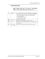
Invalid Sample Data

NOTE:

Invalid data are not used in calculations

.

However, they are saved with the other sample records. 

23a

INVALID (or 

VALID)

The condition of the data: VALID, INVALID, or INCOMPLETE. 
A sample is made invalid by one of the following conditions:

• The user has marked the sample invalid in the Sample 

Acknowledge mode

• A pump error has occurred.
• A laser error has occurred.

23b

2000/11/16

The date of the last sample

23c

14:07:06

The time of the last sample (hour:minute:second)

24a

#002

The name or number of the area that was being sampled when an 
error occurred

24b

Alarm:Pump 

(or Laser)

The type of error detected by the Lasair II particle counter

Summary of Contents for LASAIR II 350L

Page 1: ...Operations Manual P N 1000000982 LASAIR II 310A 310B 510A 350L 550L Particle Counter...

Page 2: ...870 Instrument Service Support 1 800 557 6363 Customer Response Center 1 877 475 3317 Particle Measuring Systems Europe Tel 44 0 1684 581000 FAX 44 0 1684 560337 PMSEurope pmeasuring com Particle Meas...

Page 3: ...spective owners This confidential document contains proprietary information which is protected by copyright All rights are reserved No part of this document may be reproduced distributed or transmitte...

Page 4: ...782 Germany 60005581 3 UK GB1196832 Manual Conventions NOTE A note in the text is used to highlight an item that is of operational importance to the user It is important that you observe cautions and...

Page 5: ...or Malvern WR14 1XZ Worchestershire WR13 6NN United Kingdom Distributor s Telephone FAX 011 44 1684 312950 011 44 1684 312969 Type of Equipment Particle Counter Model No Lasair II I the undersigned he...

Page 6: ...Connecting the Sample Probe 310 and 510 Versions 2 3 Connecting the Sample Probe 350L and 550L Versions 2 4 Connecting and Disconnecting the T RH Sensor 2 9 Connecting to a Computer or FMS 2 9 Chapte...

Page 7: ...ics Mode 5 18 Recipes 5 18 Main Setup Screen 5 18 Analog Data Setup Screen 5 20 Password and Remote Access Security 5 21 Communications Setup Screens Comm Setup 5 23 Comm Setup Network Page 5 24 Netwo...

Page 8: ...Interface Functions 7 11 Establishing Communications Through a Web Browser 7 12 Displaying Data on the Web Browser 7 13 Particle and Analog Data Window Control Icons and Buttons 7 15 Saving Sample Dat...

Page 9: ...9 1 Recipe Database 9 1 Sample Recipe Data 9 1 Statistics Recipe Data 9 2 Information not Saved for a Statistics Recipe 9 3 Recipe Setup Screen 9 3 Recipe Setup Screen Setup Page 9 4 Recipe Names 9 5...

Page 10: ...ollected Data Case A Erase Regularly C 6 Data Buffering C 7 Assigning Location Names C 7 Appendix D TCP IP Protocol A Brief Overview D 1 TCP IP s Network Layer D 1 Ping D 2 Appendix E Comma Separated...

Page 11: ...USB FLASH Key I 2 Appendix J 4 20 mA Input and Output J 1 4 20 mA Input J 1 Cable Pin outs J 1 4 20 mA Input Setup Values J 2 Examples of Setup for Each Accessory J 2 4 20 mA Output J 3 4 20 mA Output...

Page 12: ...ss M 6 Setting the TCP IP Address in a Touch RAM Button M 7 Rules for Reading Touch RAM Buttons M 7 Setting TCP IP Address with a Touch RAM Button M 9 Older Touch RAM Buttons M 9 Accessories M 9 Appen...

Page 13: ...Table of Contents xii This page is intentionally left blank...

Page 14: ...re 5 9 Alarm Setup Screen Analog Alarms Page 5 17 Figure 5 10 Main Setup Screen 5 18 Figure 5 11 Analog Data Setup Screen 5 20 Figure 5 12 Sampling Setup with Password Active but not Entered 5 22 Figu...

Page 15: ...ibration Warning Dialog Box 10 5 Figure B 1 Comm Setup Network Screen B 3 Figure H 1 Comm Setup Network Dialog Box H 2 Figure H 2 Comm Setup Data Dialog Box H 2 Figure I 1 Status Screen with Valid USB...

Page 16: ...ntout Legend 6 15 Table 8 1 EU GMP Class Standards 8 4 Table 8 2 ISO Classes Corresponding to EU GMP Classes 8 4 Table 8 3 FS 209 Class Standards 8 6 Table 8 4 BS 5295 Sample requirements 8 7 Table 8...

Page 17: ...List of Tables xvi...

Page 18: ...nlet The sample flow is controlled to maintain 1 CFM 50 LPM for the 350L and 550L of airflow through the sampler A variance of only 5 in airflow is allowed in a valid sample Model No Channel Threshold...

Page 19: ...lightweight and durable airborne particle counter Its compact size and comfortable carrying handle enhances its portability The Lasair II particle counter can be used for the following applications C...

Page 20: ...pling process from a remote computer by means of Particle Measuring Systems Facility Net1 software The Lasair II particle counter stores 3 000 sample records in Random Access Memory When connected to...

Page 21: ...display LCD screen The display screen is covered with an inert clear plastic cover that reduces glare and is easy to clean Control Panel The control panel is located below the display screen and is co...

Page 22: ...log sensors can be connected through the 4 20 mA port to provide additional environmental sensor information Analog sensors available from Particle Measuring Systems include air velocity differential...

Page 23: ...cates with a remote facility monitoring system RS 232 Port The RS 232 port is used for calibration sensor control or TouchRAM communications Each kind of connection requires its own cabling configurat...

Page 24: ...ative blower pump is located at the base of the unit The pump is a low power DC voltage controlled unit that is controlled to keep the flow rate at one cubic foot per minute This pump was selected for...

Page 25: ...mum concentration models 310A and 325 375 000 ft 3 at 5 coincidence loss Counting efficiency Models 310A 310B and 510A 50 10 exceeds JIS standard Zero count level 1 count 5 minutes at minimum size mee...

Page 26: ...nter Built in thermal printer Reports Sample printouts final reports for EU GMP ISO 14644 1 FS 209E and BS 5295 Power 100 240 V 10 50 60 Hz 1 25 A maximum Battery optional Removable NiMH battery 16 8...

Page 27: ...II particle counter 350L and 550L 3 hours with 10 feet of tubing on the inlet jet one minute samples and a printout every sample 3 5 hours with no tubing and no printout after every sample Battery ch...

Page 28: ...f the shipping container appears to be in good condition continue to carefully unpack the container while inspecting the contents for damage Ensure that the items listed above are included in your shi...

Page 29: ...to the electrical requirements Ensure the main supply is properly grounded To connect power for the particle counter 1 Plug the female end of the cord into the power inlet The inlet is located on the...

Page 30: ...door NOTE To completely remove Lasair II particle counter s power the battery pack must be removed Connecting the Sample Probe 310 and 510 Versions The Lasair II particle counter comes with a standar...

Page 31: ...gently move it side to side while pressing down until it reaches the base of the inlet 3 Connect the adapter optional onto the free end of the tubing 4 Fit the sample probe over the adapter inlet To s...

Page 32: ...o MI008 A table tripod Part No 1000000979 A wall mount adaptor for the Standard Sampling Probe Part No 1000000971 A Sampling Probe Isokinetic with wall hand tripod adapter Part No 1000008907 from Part...

Page 33: ...of the Tubing on page 2 7 3 Fit the sample probe over the open end of the sample probe adapter The sample probe s internal O ring will hold it securely to the adaptor 4 Remove the protective cap from...

Page 34: ...Installing the Particle Counter Lasair II Particle Counter Operations Manual Page 2 7 Figure 2 5 350L and 550L Assembled Sample Probe end of the Tubing...

Page 35: ...the sample probe to a tripod 1 Fit the screw on the tripod plate into the threaded hole on the tripod adapter 2 Make the screw secure but hand tight only 3 Position the tripod where you wish to sampl...

Page 36: ...nsor straight down into the connector You should hear a slight click as it locks into place To disconnect the T RH sensor 1 Grasp the cylindrical sleeve at the base of the sensor and pull up The sleev...

Page 37: ...Page 2 10 Lasair II Particle Counter Operations Manual Chapter 2 Unpacking and Installation This page is intentionally left blank...

Page 38: ...reens Menu options Display screens Front Panel Layout By using the control panel keys and softkeys you can perform all of the tasks necessary to set up and operate the Lasair II particle counter In th...
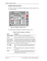
Page 39: ...sampling Press the Stop key To activate the edit mode on a setup screen Press the Enter key To move the cursor while in edit mode press the Left or Right arrow key To increase or decrease a value whi...

Page 40: ...tup Main Setup Status Analog Print Alarm Setup Statistics Setup Recipes Setup Analog Data Setup 4 20 mA Output Setup optional Network Setup Page Serial Port Setup Page Data Display Setup Page Data Tab...

Page 41: ...een A screen that can be edited opens in the Display Mode The screen must be set to Edit Mode before you can change an input field To change an input field enter Edit Mode by pressing the blue Enter b...

Page 42: ...the Up Arrow softkey you will eventually arrive at the Main display Display Layout The Main Display Screen is divided into four areas A top reporting banner that displays the location date run time st...

Page 43: ...e When the Initial Delay time reaches 0 sampling begins The sample time counts down to zero from the sample time you have set A clock symbol is displayed to the left of the sample time If the sample i...

Page 44: ...is the symbol for a user password When no password has been set the padlock is greyed out If a password has been entered the padlock icon takes on the color blue If the password has been entered but...

Page 45: ...od is installed into the Lasair II particle counter the battery status may display for about 5 minutes The recycle field shows how many charge discharge cycles the battery pack has been through The ex...
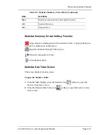
Page 46: ...w temperature and relative humidity values To view the Analog Data Display Screen press the softkey to the right of the Analog Data display icon fourth icon A sample Analog Data display screen is show...

Page 47: ...een press Location Name Sampling Setup 1st top softkey Sampling Time Vol Sampling Setup 1st softkey Delay Times Sampling Setup Advanced 1st softkey Sampling Units Sampling Setup Advanced 1st softkey R...

Page 48: ...an now change or keep the current sampling setup values 4 Press the Tab Right softkey once to move to the Sample Size box Take a 1 00 minute or a 1 0 cubic foot sample as follows 5 Press the Right key...

Page 49: ...Page 4 2 Lasair II Particle Counter Operations Manual Chapter 4 Taking a Quick Sample Software Version 2 0 This page is intentionally left blank...

Page 50: ...en Set the communications protocol mode and enter the addresses for connections to a computer or to facility monitoring software 4 20 mA input and Output Refer to Appendix I Statistics Setup Refer to...

Page 51: ...d Editing Softkey Icon Functions The Delete softkey deletes the alphanumeric character to the left of the cursor and moves the cursor one space to the left Depending on the kind of field you are editi...

Page 52: ...l icon in the upper left corner If the icon is present the screen is a setup screen and values can be changed 2 Press the Enter key to enable the Edit Mode 3 Press the Tab Keys to move the cursor to t...

Page 53: ...tion name Sample size Number of samples Continuous sampling Print average of samples Group repeat mode Print sample report Advanced Page Setup Functions Sample type Initial delay Purge delay Inter sam...

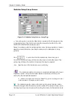
Page 54: ...elect the Infinity icon Print the sample average Select this icon to calculate and print a sample average at the end of a series of samples Group Repeat Continuously collects a finite number of sample...

Page 55: ...rformed in every cycle AutoPrint Select this icon to automatically print at the end of each sample When On the Printer icon is visible When Off the icon is greyed out NOTE The delay time between sampl...

Page 56: ...en samples plus the sample time must be at least 15 seconds to allow enough time for the printer to finish the last job Units ft 3 Cubic feet Enable this icon to display sample data by cubic feet m3 C...

Page 57: ...tically shut down the laser and pump to reduce wear The auto print function remains under user control To enable the start by time of day time feature 1 From the Sampling Setup Screen press the Enter...

Page 58: ...n on the main screen See below The pop up selection box allows the user to set the number of particles per beep 1 10 100 100 000 or turn the mode off Thus if an area has so many particles that the bee...

Page 59: ...option can also be used to download a file of location names from a computer into the particle counter See Chapter 7 Location setup options are as follows Each setup option is represented by an icon a...

Page 60: ...From the Location Name Setup screen press the Add Location softkey The Add Location Screen will be displayed NOTE If an existing location name was highlighted when you pressed the Add Location softke...

Page 61: ...he cursor Pressing the Up or Down Arrows change the alphanumeric value 4 When editing is complete press the Enter button on the control panel to highlight the OK button 5 Press the Enter button again...

Page 62: ...e Analog Data Display Screen if it is an analog value To stop the red and yellow flashing After the pump stops press the Enter button once more after pressing it to silence the alarm You can also sile...

Page 63: ...alog environmental sensor Analog data information is set up in the Analog Data setup screen Each limit can be enabled or disabled Printing on Alarm This feature automatically prints one of the followi...

Page 64: ...ck and forth from Particle Alarms and Analog Alarms press the Tab softkey when you are out of edit mode Setting Particle Alarms You can set as many as six particle alarms one for each particle size ch...

Page 65: ...the 1 0 radio button The alarm setting is now enabled Automatic Changes in Particle Alarms Particle alarm settings will be automatically adjusted for changes made in the sample settings so that the pr...

Page 66: ...ode 3 Tab to the first Min value field in the list Use the directional arrow buttons on the control panel to move around the list of variables 4 Press Enter to initiate the ability to change an alarm...

Page 67: ...button to print the sampling parameters The Statistics Mode Pressing the softkey for the statistics mode symbol opens the Statistics Setup Screen For details see Chapter 8 Statistics Mode Recipes Pre...

Page 68: ...is always enabled for the web browser connection Language Select English French Spanish German Italian Japanese Kanji Korean or Mandarin classical Data Erase button Pressing this button erases all st...

Page 69: ...for more information about changing values and selecting options in the fields Analog Data Setup Screen To display the Analog Data Setup Screen 1 Press the second softkey on the Main Display Screen Th...

Page 70: ...ling Setup screen restriction is intended to be used with recipes See Chapter Table 5 2 Analog Data Setup Screen Fields and Buttons Field or Button Function T rh Enables or disables the optional Tempe...

Page 71: ...and is the same password that users must enter when accessing the particle counter from a web browser or Facility Net Remote access from a web browser or from a facility management program such as Fa...

Page 72: ...enable password protection navigate to the Enable Password check box and then press the Enter button to insert a check mark Communications Setup Screens Comm Setup To open the Comm Setup Screens 1 On...

Page 73: ...serves A valid IP address would look like 010 255 000 099 The non significant zeros can be dropped so that the same address appears as 10 225 0 99 Mask Sets the net mask address using a decimal notati...

Page 74: ...able TCP IP The default setting for this field is Enable note the check mark in the box It allows a user to connect to Facility Net Disabling this function prevents the use of these applications TCP I...

Page 75: ...ing the unit for data For more information see Appendix F PMS Multi Drop Protocol MiniLaz Emulation TouchRAM Read Select this button to read TouchRAM buttons only For more information see Appendix M T...

Page 76: ...N OFF button in the lower right of the control panel You will hear a beep during the startup process 3 When the display is visible press the green Start button on the control panel You will hear the p...

Page 77: ...a on the Data Table Screen Data stored in the Lasair II particle counter can be viewed on the Data Table Screen If no filter parameters have been set all stored data will be available for review in th...

Page 78: ...ticle Counter Operations Manual Page 6 3 2 Open the Data Table Screen by pressing the Data Table icon softkey The Data Table Screen will open and after a few seconds data will fill the table cells Fig...

Page 79: ...ata Table Screen see above displays all stored particle and analog data or the subset of the data you select to view To enable the table s navigation mode press the Enter softkey In the edit mode pres...

Page 80: ...the sample was completed in the format HH MM SS Location the location name assigned to the sample data Sample duration the duration of the sample in the format HH MM SS Sample volume the volume of air...

Page 81: ...key on the next screen 2 Open the Data Display Setup Screen by pressing the Data Display icon softkey The Data Display Setup Screen will open The options in the Data Display Setup Screen allow you to...

Page 82: ...mple data was created Select Location to sort by the location where the sample was collected Before selecting sort by location location names must have already been created and assigned to the sample...

Page 83: ...the Start and End settings time data that was generated on or between two user entered dates and times by location a combination of user entered dates times and locations Figure 6 4 Data Filter Time S...

Page 84: ...ltered but you are unable to advance to the date filter field it probably means that someone has changed the instrument date after some data had been stored in memory 7 Use the right and left arrow ke...

Page 85: ...activate the Edit mode NOTE The edit mode will open with the global Data Filter 1 0 button highlighted and enabled 3 Press the Tab Forward icon softkey to advance to the Location Filter 1 0 button 4 P...

Page 86: ...f records displayed will be assigned new Row Index numbers to reflect the number of records displayed These Row Index numbers will only have meaning for the displayed subset The Row Index numbers for...

Page 87: ...osen and then averages them NOTE As many as 100 records can be printed 2 Assuming that you want to print more records than the first one press the Tab Forward icon softkey as needed to advance to the...

Page 88: ...n the Start and Number digits are correct use the Tab Forward softkey to advance to either the Print Records button or the Print Average button Press the Enter softkey to select the option of your cho...

Page 89: ...riptions are listed by line number from top to bottom as the lines appear on the printed output Note however that the lines are not numbered on the printer output A description of each line and the po...

Page 90: ...lidates the sample Also see lines 17 and 18 4 2007 12 06 12 01 00 Start of the sample 5 2007 12 06 12 01 05 1 A date stamp year month day followed by a time stamp hour minute second when the sample en...

Page 91: ...alue or on the Analog Data Display Screen if it is an analog value 12 10 0 16084 16084 The 10 micron channel total counts of 10 microns total counts 10 microns 13 Avg Min Max Column headers for Enviro...

Page 92: ...y full Remember once the data file is full you will lose the oldest data when new sample data is collected Monitoring the Sample Data File To monitor status from the particle counter Follow these step...

Page 93: ...ly from Lasair II particle counter memory The erase function erases all data from memory without possibility of recovery Data can also be erased by means of the browser interface See Deleting Sample D...

Page 94: ...unter Operations Manual Page 6 19 2 From the Main Setup Screen enable the edit mode and click the Data Restore Button The Unerase Data Dialog box will open confirming the number of records restored 3...

Page 95: ...Page 6 20 Lasair II Particle Counter Operations Manual Chapter 6 Operation This page is intentionally left blank...

Page 96: ...unications Details of using the different communication methods Communications Overview The Lasair II particle counter provides several methods for communicating with external computers They are outli...

Page 97: ...older Lasair communications interface but it has been enhanced with status feedback messages See Appendix F PMS Multi Drop Protocol MiniLaz Emulation This is a second RS 232 protocol which can be ena...

Page 98: ...parameters are set and various network communication protocols are enabled or disabled When a network address is changed the particle counter must be rebooted A pop up message informs you of this whe...

Page 99: ...valid gateway address is 10 255 0 60 If this is blank the instrument will be unable to communicate outside the local network Multicast The multicast address must be assigned if you are using Facility...

Page 100: ...ppendix H Pharmaceutical Two channel Output Mode Serial Communication Setup Screen This screen allows selection of the RS 232 port interface protocol and other serial communications selections Changes...

Page 101: ...ore location and sampling parameters for the Lasair II particle counter For additional details see Comm Setup Serial Screen on page 5 25 and Appendix M Touch RAM TouchRam Read Write This is a second s...
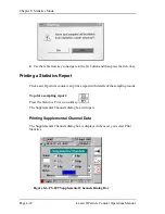
Page 102: ...maceutical Two channel Output Mode Using the Remote Mode Remote mode means that Lasair II particle counter will not be permanently connected to any other communications or control network while it is...

Page 103: ...entification to your Facility Net system the driver will ask if you want to switch the existing configuration over to the new IP address The Lasair II particle counter identification is placed in the...

Page 104: ...le point The All analog entries are optional The driver will auto configure these locations and download data from the Lasair II particle counter to Facility Net When download is complete Facility Net...
Page 105: ...e of more than one person accessing the same Lasair II particle counter should be managed through passwords and other administrative controls Preparing for On Line Operation To prepare the particle co...

Page 106: ...uring Systems representative Controlling the Particle Counter with Browser Software You can use your web browser software to control the Lasair II particle counter from a separate computer through one...
Page 107: ...e with a remote connection The Lasair II particle counter should always be left with the Main Display Screen open To establish communications Follow these steps to establish communications between a c...

Page 108: ...wise click OK The main Lasair II display will open NOTE If a password has been assigned it is always enabled in the web browser even if it is disabled on the Main Setup Screen Displaying Data on the W...

Page 109: ...Lasair ID sampling location name and the results of the current or previous sampling Unlike the data displayed on the Lasair II instrument the data displayed on the web browser is not real time While...

Page 110: ...ontrol Icons and Buttons The Control Icons and buttons control the following functions Saving Sample Data File The sample data file may be copied to another file so it can be saved for long term reten...

Page 111: ...arated Value CSV Format 2 Click on File Save As in the browser s menu bar 3 Complete the dialog box to name the new data file and to define where the file will be located For example you might name th...

Page 112: ...sage that reads Unable to gain control of the instrument at this time No values were updated means that someone else has direct control of the Lasair II particle counter or that the particle counter h...

Page 113: ...air II Particle Counter Operations Manual Chapter 7 The Used line of the storage indicator will be zero indicating that all records have been deleted Setup Windows To open the Setup page click on the...

Page 114: ...o button associated with the choice Click in an empty radio button to choose the option associated with it Parameter Values The parameter values are changed by using a pull down menu or by clicking an...

Page 115: ...ile to Lasair II particle counter copying location names from Lasair II particle counter to a file Copying Location Names from a File You may find it easier to create location names on a text editor a...
Page 116: ...n to open the Location Name Setup Window 5 Click on the Transfer locations to Lasair II from a file icon 6 Follow the instructions on the window to specify the file you want to transfer to the Lasair...

Page 117: ...ly approximate when used with a Lasair II particle counter The native Lasair II particle counter delay counts from the end of one sample to the start of the next while the MiniLaz counts from the star...

Page 118: ...n data from one or more locations The settings that may be changed vary with the standard or Average mode If a standard does not allow change to a variable that variable will be disabled in the setup...

Page 119: ...he following screens are functionally changed when the statistics mode is enabled Sample Setup Screen Sample size is locked when the statistics mode is enabled Also samples are all by volume not time...

Page 120: ...es specified in the document s tables have been implemented The Lasair II particle counter does not support intermediate class sizes or intermediate particle sizes Use the following sources for more i...
Page 121: ...ns For Grade A the sample volume is a Minimum Total of 1 m3 For Grade C or Grade D the sample volume is the same as ISO Simultaneous EU GMP and ISO The EU GMP ISO mode allows the user to sample the cl...

Page 122: ...esigning the FS 209 module and only the classes specified in the document s tables have been implemented If the number of locations is less than five the number of samples required at each location is...

Page 123: ...www iest org Table 8 3 FS 209 Class Standards Maximum Particles Per Unit Volume Class 0 1 0 2 0 3 0 5 5 0 SI Englis h m3 ft 3 m3 ft 3 m3 ft 3 m3 ft 3 m3 ft 3 M1 350 75 7 30 9 10 0 M1 5 1 1 240 35 0 2...

Page 124: ...the min max sample volume is 27 4 Liters 0274 m3 In BS 5295 mode the statistics summary screen and statistics location summary only show data for the smallest particle channel Data for all relevant c...

Page 125: ...bal alarms are automatically disabled They can however be manually enabled while in statistics mode When the statistics mode is disabled global alarms will not be automatically re enabled If the globa...

Page 126: ...t you can build a picture of the layout Sampling Setup Main Setup Status Analog Print Alarm Setup Statistics Setup Recipes Setup Analog Data Setup 4 20 mA Output Setup optional Data Table Sample Setup...

Page 127: ...ling Setup screen will open 2 Press the Statistics Setup icon softkey to open the Statistics Setup Main page Statistics Setup Main Screen Name Enter the name of the area that will be certified Example...

Page 128: ...tion can be changed while the statistics mode is enabled ABC or 1 2 3 Select ABC or 1 2 3 ABC will select either location names or location numbers This option cannot be changed once statistics has be...

Page 129: ...rtified uni directional or multi directional This setting may influence the number of locations that must be sampled Area Input the size of the cleanroom you are certifying The minimum number of locat...

Page 130: ...ave set up the Lasair II particle counter for sampling operation is a simple matter Use the following steps to operate the particle counter Collecting Sample Data To collect sample data 1 After settin...
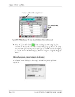
Page 131: ...the unit will begin sampling The sampling process and the results of sampling can be observed on the Main Display When the sample is complete the pump stops When Sample Acknowledge is Activated If yo...

Page 132: ...f Lasair II particle counter Location Names Numbers When the first sample is complete the following dialog box will display To continue sampling 1 Record a description of where the first sample occurr...

Page 133: ...tored in the location name list starting with the location name highlighted in the Sampling Setup Screen For example if 10 location names exist and sampling starts at the seventh name sampling will pr...

Page 134: ...buttons to highlight the location name you want to use for the next sample 5 Accept the location name and navigate to the Main Display 6 Move the particle counter to the location that matches the loc...

Page 135: ...locations completed Total number of locations and Minimum number of locations Example 5 locations have been completed The total number of locations planned to be sampled was five The minimum number o...

Page 136: ...n the Analog Data Screen Print Statistical Data Statistics Data Table Screen This screen displays location status To open the Statistics Table 1 From the Main Display press the Statistics icon softkey...

Page 137: ...to acknowledge the dialog box Figure 8 5 Statistics Table Screen Click these softkeys to see the previous 10 records or the next 10 records The number of samples collected at a location These numbers...

Page 138: ...or certification is found to be hopelessly out of specification when you are done sampling To disable the statistics mode 1 Navigate to the Statistics Setup Setup screen 2 Enable the edit mode by pres...

Page 139: ...cs Report The Lasair II particle counter can print a report with details of the sampling results To print a sampling report Press the Statistics Print icon softkey The Supplemental Channels dialog box...

Page 140: ...ter s Statistics Report generated when a room is certified to the ISO 14661 1 standard The lines have been numbered to allow a more comprehensive description of the information provided below the prin...

Page 141: ...r of locations to be sampled 10 Planned Samples Location 2 Number of samples per location 11 Min Sample Volume 0 0283 cm Minimum volume to be sampled 12 Volume Sample Volume taken per sample 13 Status...

Page 142: ...INCOMPLETE A sample is made invalid by one of the following conditions The user has marked the sample invalid in the Sample Acknowledge mode A pump error has occurred A laser error has occurred 23b 2...

Page 143: ...Page 8 26 Lasair II Particle Counter Operations Manual Chapter 8 Statistics Mode This page is intentionally left blank...

Page 144: ...statistics setup information into battery backed up RAM and then assigning the setup an associated recipe name Recipes can be saved from the Recipe Setup Screen or from the sampling or statistics set...

Page 145: ...e probe units C or F Alarms On Off Alarm Buzzer On Off Particle Alarm Type Differential Cumulative For Each Particle Size Alarm Setting Alarm On Off For Each Analog Channel Statistics Recipe Data The...

Page 146: ...ameters The number of samples is automatically set when statistics are enabled except for average mode In average mode the current sample count is used if possible Alarm settings By default alarms are...

Page 147: ...tistics recipe may be re written with a sampling recipe and vice versa A copy of this button is also on the Sampling Setup Screen for convenience in creating new sampling recipes This button saves the...

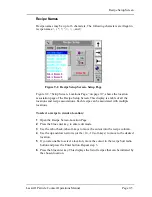
Page 148: ...ted with multiple locations To select a recipe to run at a location 1 Open the Recipe Screen Location Page 2 Press the blue enter key to enter edit mode 3 Use the tab or back tab soft keys to move the...

Page 149: ...ion name you want to disassociate is highlighted in blue 2 Use the up pointer to move to the blank entry at the top of the list 3 Press the enter button The recipe name alongside the location name wil...

Page 150: ...he recipe is a statistics recipe a pop up dialog box will appear after loading asking whether to enable the statistics mode When a recipe is tied to a location selecting the location will automaticall...

Page 151: ...he Lasair II will attempt to set the particle alarms based on the original instrument However if alarms were set on sizes not on the new instrument they cannot be set When loading a statistics recipe...

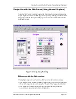
Page 152: ...s both setup pages from the front panel The page is accessed in a similar manner to the front panel control Differences with the Web version Sampling recipes are not shown in a different color than st...

Page 153: ...h line containing a single location name The first line contains the number of location names in the file The location names must start at the beginning of the line The file can be edited with a text...

Page 154: ...net Explorer Lasair II Particle Counter Operations Manual Page 9 11 associated recipe will be removed from the location This file can be edited using a text editor or Excel and then saved as a CSV fil...

Page 155: ...Page 9 12 Lasair II Particle Counter Operations Manual Chapter 9 Recipes This page is intentionally left blank...

Page 156: ...ting The Lasair II particle counter is designed to be easily cleaned with common cleaning chemicals Particle Measuring Systems has also performed compatibility testing with cleaning and disinfecting a...

Page 157: ...Kydex a rugged plastic in the PVC family The polyester display screen is sealed around its edges and all case openings are sealed with gaskets Both Kydex and polyester are resistant to most cleaning c...

Page 158: ...Lasair II particle counter The battery battery enclosure Temperature Relative Humidity sensor and the printer enclosure can be cleaned the same as the other parts of the particle counter NOTE The bat...

Page 159: ...rtant to maintain the maximum correlation between the battery charge indicator and the actual battery charge you can also purchase and use the optional external battery charger BC II See Appendix K Ac...

Page 160: ...b server If the calibration date past due 365 days since the last calibration date the message will include the number of days the calibration is past due The instrument also notifies the user if no c...

Page 161: ...Page 10 6 Lasair II Particle Counter Operations Manual Chapter 10 Maintenance This page is intentionally left blank...

Page 162: ...ed strip of paper try the following steps 1 Ensure that there is a roll of paper in the paper enclosure 2 Ensure that the paper roll is free to rotate within the paper enclosure 3 Ensure that the end...

Page 163: ...not correct itself test your power source 3 If the power source appears to be adequate look for obstructions in the Lasair II particle counter s intake port exhaust port and sample tubing Remove any o...

Page 164: ...ort H The Lasair II particle counter will not run on battery power NOTE When running on battery power if the recharging circuit senses that the battery charge is inadequate to support sampling the Las...

Page 165: ...e do the following 1 Remove the battery from its enclosure and examine the contact points on the battery and in the enclosure Look for signs of obstruction or contamination If you find contamination c...

Page 166: ...web browser to Lasair II particle counter interface the web page does not update properly Internet Explorer 5 x saves the image of a page when you open it The next time you open that page Internet Exp...

Page 167: ...he Web Server in the following conditions if the instrument is being run from front panel if LCD screen is on one of the setup screens Q Facility Net will not connect to the particle counter 10 Ensure...

Page 168: ...runs one of the three common operating systems Windows UNIX or Apple If the computer is a palm size or hand held device it must run the Windows CE operating system Software Requirements The computer...

Page 169: ...resses to both the Lasair II particle counter and the computer to which it will be connected It may also be necessary to specify other types of addresses such as gateway and multicast After changing T...

Page 170: ...Navigate to the Mask address and set its address according to your network administrator s directions 6 Navigate to the Enable Web Server check box and press the Enter softkey to place a check in the...

Page 171: ...mark in the box It allows access to the Lasair II particle counter from a web browser such as Internet Explorer or Netscape Navigator Disabling this function on the unit removes the ability for remote...

Page 172: ...network component NOTE There may be more than one TCP IP network component Choose the one that corresponds to the network card 4 Select Properties The TCP IP Properties dialog box will open 5 Select t...

Page 173: ...section explains how to connect to the Lasair II particle counter over an Ethernet network and configure the TCP IP The steps are the same except for the two following items Instead of a crossover ca...

Page 174: ...icle counter is in a fixed monitoring position all data comes from the same location Preparations for Setup Ensure the unit identifier on the Lasair II particle counter Main Display Screen is unique a...

Page 175: ...et ports on the particle counter and the computer 3 Configure Facility Net for Lasair II particle counter 4 Sampling points are automatically created for all Lasair II particle counter location names...

Page 176: ...Multiple Locations 5A 1 Configure Facility Net Set Sensor to Lasair II Set Text All Data 1 Select Configure Instruments 2 Select Add then select the Add Network tab 3 a Enter the specific IP address i...

Page 177: ...tup display screen 5A 2 Select OK OK and accept all changes Immediately Facility Net will do the following Retrieve the Lasair II particle counter s Location Name file and automatically configure each...

Page 178: ...OK and accept all changes 5B 3 Immediately the Facility Net software will take control of the Lasair II particle counter and do the following Sample according to the current Facility Net settings NOT...

Page 179: ...ded from a Network Station Mobile Collected Data Case A Erase Regularly Facility Net is unable to interleave data arrange data in a non contiguous way to increase performance from overlapping chronolo...

Page 180: ...Assigning Location Names Some forethought is required when designing a Facility Net system Each instrument s address may be associated with up to 256 locations For smaller systems it may be adequate t...

Page 181: ...Appendix C Downloading Data to Facility Net Page C 8 Lasair II Particle Counter Operations Manual This page is intentionally left blank...

Page 182: ...ultiple networks are connected together it becomes necessary to use routers or bridges to send communication packets from one network to another A more complex protocol such as TCP IP becomes necessar...

Page 183: ...run from a Windows DOS window To use the Windows for Workgroups TCP IP PING 1 With Windows running open a DOS window by double clicking on the MS DOS Prompt icon 2 At the DOS prompt type PING IP ADDR...

Page 184: ...me of the room in which the statistics were taken and the type The type can be FS 209E ISO 14644 1 EC GMP EC GMP and ISO BS 5295 or AVERAGE The room name is added before the statistics type with a sep...

Page 185: ...he instrument 27 Counts 5 ditto 28 Size 6 This is fixed for the instrument 29 Counts 6 ditto 30 Number Analog This can vary from 0 to 6 depending upon what is enabled on the instrument To prevent colu...

Page 186: ...obe is rh 37 Units 2 See above 38 Avg 2 See above 39 Min 2 See above 40 Max 2 See above 41 Name 3 Analog channel name Channel 3 is the first of four user channels 42 Units 3 See above 43 Avg 3 See abo...

Page 187: ...Appendix E Comma Separated Value CSV Format Page E 4 Lasair II Particle Counter Operations Manual This page is intentionally left blank...

Page 188: ...not work properly Tested RS 232 RS 485 converters Both of these models have been tested with the Lasair II particle counter in MiniLaz emulation mode connected to Facility Net NOTE A null modem is re...

Page 189: ...rly format a command code 1 Add the address of the instrument to the beginning of the command string The address is an unsigned 16 bit integer between 0 and 99 2 Add a 16 bit checksum of the data and...

Page 190: ...off then number of samples is set to one Use CNOS to set number of samples CDT yy mm dd hh mm ss Set date and time Either two digit or four digit year is ok Response RDT CES End Sampling Response RES...

Page 191: ...m Get number of samples in queue and 0 1 for sampling 1 or not sampling 0 CSN Response CSN s_n Returns the Lasair II particle counter serial number CSR Response RSR Causes instrument to reboot about...

Page 192: ...n in feet3 CF Causes the Lasair II particle counter to sample by CF and to sample by volume Maximum value 1439 CF Minimum value 0 1 CF Multi Drop CTD Command Data Format This data format is identical...

Page 193: ...parated Value CSV Format C5 Channel 5 Raw Differential Counts TM Temperature Degrees F RH Relative Humidity percent RTD2 Date Time Sensor_Name Sensor_Type Sensor_S N Statistics Loc_chg Location Manifo...

Page 194: ...flow control CTRL Q CTRL S is used A command prompt of is output between commands and data packets Automatic data output is generated All commands return either an OK or an error response followed by...

Page 195: ...r Upgrade Information The original Lasair had a somewhat terse interface hence users who want to upgrade their own software must handle the fundamental interface changes The following is a quick list...

Page 196: ...r of hours minutes and seconds to avoid problems C 10 sec Set Sample Time Seconds Set sample time in order of hours minutes and seconds to avoid problems This command returns a Range Error if sec 6 an...

Page 197: ...d C Commands C commands dealing with alarms and manifold control are not supported Manifold control with the Lasair II particle counter requires an AM II and Ethernet control 15 Group print 17 Count A...

Page 198: ...se commands split internal variables into several pieces For instance C 0 through C 6 are used to set date and time Because of the variable split unexpected results can be obtained if the user is not...

Page 199: ...ion parameters for 4 20 mA analog input channel Minimum value engineering units value at 4 mA Maximum value engineering units at 20 mA ANSCALE n scale Set 4 20 mA scale for analog input channel ANOFFS...

Page 200: ...IVER Return the instrument firmware version KB 1 0 Keypad lockout enable disable Lockout is retained through a power cycle If this lockout is disabled with the KG 0 command it will be re enabled when...

Page 201: ...ill cause an immediate printout analog alarm particle alarm pump error laser failure The printout lists the alarm condition the location and date time SS Start sampling SN Set to continuous sampling w...

Page 202: ...format UNITS F M Set particle volume units to either feet3 F or meters3 M This affects displaying normalized data on the LCD and setting alarms in normalized data mode This command is independent of...

Page 203: ...Appendix G Native Serial RS 2332 Communications Page G 10 Lasair II Particle Counter Operations Manual This page is intentionally left blank...

Page 204: ...ill only include these two channels Otherwise all six channels of data will be transmitted Alarms Alarms for all six channels are still available It is advisable however to ensure that only cumulative...

Page 205: ...y until the Comm Setup Data dialog box opens To allow only 2 channel data to be output to Pharmaceutical Net 1 Press the Enter key to enable the Edit mode The 0 5 m 5 0 m check box will be highlighted...

Page 206: ...armaceutical Net during initial communications over TCP IP It is not however stored Print Output This special pharmaceutical mode output applies to standard printouts and statistics average data print...

Page 207: ...Appendix H Pharmaceutical Two channel Output Mode Page H 4 Lasair II Particle Counter Operations Manual This page is intentionally left blank...

Page 208: ...keyboard can facilitate set up and operation The keyboard s F1 key is used for the top most softkey The F5 key is used for the bottom most softkey USB FLASH Key Devices Sample data can be copied to th...

Page 209: ...ds are plug and play In other words when connected to the USB port the keyboard is immediately ready for use without any set up Copying Sample Data to a USB FLASH Key The FLASH data storage function i...

Page 210: ...is formatted in the standard CSV format for the Lasair II particle counter The following points should be kept in mind when using a FLASH Key for file storage There is no mechanism for deleting copyi...

Page 211: ...Appendix I USB Host Port Page I 4 Lasair II Particle Counter Operations Manual This page is intentionally left blank...

Page 212: ...e Use this appendix to find the following information Cable Pin outs Standard PMS Cable Pin Number Pin Use Temperature 1 Analog signal 1 input 2 Analog signal 1 GND 3 12 24 VDC Relative Humidity 4 Ana...

Page 213: ...ative Humidity R H Differential Air Pressure DAP Air Velocity English Metric Range 0 100 F 5 to 55 C Scale 6 25 3 75 Offset 0 5 Units F C Range 0 100 Scale 6 25 Offset 0 Units English Metric Range 0 0...

Page 214: ...4 0 or newer supports 4 20 mA output This feature is enabled and configured from the 4 20 mA Out Setup Screen NOTE Use of this feature requires that an optional 4 20 mA board be installed in the unit...

Page 215: ...will appear to be below the LCD s surface 4 Navigate to the first Scale field by pressing the Forward Tab softkey once 5 Use the Up and Down softkeys to move to the field you want to change Table J 1...

Page 216: ...greater than zero 9 Use the Up and Down softkeys again to navigate to the next Scale Field you want to edit 10 Repeat steps 6 9 until all Scale fields have been correctly set 11 Press the Enter button...

Page 217: ...utput Channel Output Return Definition Channel 1 1 2 Status and alarm information Channel 2 3 4 Manifold position Channel 3 5 6 Particle channel 1 smallest size Channel 4 7 8 Particle channel 2 Channe...

Page 218: ...l is 0 25 mA Thus channel 1 is 4 25 mA and channel 32 is 12 mA Notes on Setting Particle Scale Factors Channel Particle Scale Considerations The maximum counts that can be monitored is the same as the...

Page 219: ...e between setting the scale large enough to cover the worst case expected count output while at the same time setting it small enough to accurately show normal events Example The user would like to di...

Page 220: ...0L 1000008908 MP Adapter Probe to Lasair II particle counter 350L 550L 1000008909 MP Adapter probe to tubing Lasair II particle counter 350L 550L 1000008907 MP Adapter 1 2 inch barbed tubing to Lasair...

Page 221: ...nformation on return and collection systems in your area For California consumers contact Particle Measuring Systems Customer Service Department at 877 475 3317 for instructions on returning used rech...

Page 222: ...he audible buzzer To set the selector switch 1 If your instrument is the Lasair II particle counter plug the DB connector from the HHIPA into the Lasair II particle counter s HHIPA connector 2 If you...

Page 223: ...n sampling with the HHIPA thumbwheel switch set to 0 5 When a leak is found adjust the thumbwheel switch until you can count the number of flashes beeps per second to get a rough idea of the severity...

Page 224: ...r example are not compatible with Touch RAM The button can be permanently attached to the wall near a sample point location When the button is read with a special wand reader the sampling parameters a...

Page 225: ...nt service and is not intended for customer use SIO Baud Menu This menu is selectable from 1200 38400 All communications use 8 data bits one stop bit and no parity For Pharmaceutical Net select 9600 b...

Page 226: ...and the Enter key to enable TouchRAM Read Write 2 Attach the Touch RAM wand to the RS 232 connector 3 Navigate to the Location Setup Screen NOTE The Location Setup Screen will already be in Edit mode...

Page 227: ...rticle counter s largest channel Particle alarms in metric units written by the MiniLaz cannot be converted to meaningful particle counter alarms MiniLaz buttons support temperature and rh alarms but...

Page 228: ...d Print Average Flag Older software will read Default 0 GLOBAL_ALARMS Enabled Buzzer_Enabled PARTICLE_ALARMS Use_differential CH3_Counts CH5_Counts CH1_Counts CH3_Enabled CH5_Enabled CH1_Enabled CH4_C...

Page 229: ...in an instrument with different size channels will give different alarm settings This is true even if the instruments are in a two channel pharmaceutical mode 0 5 and 5 0 channels only Flow rate Butto...

Page 230: ...To read a button the serial setup must be either TouchRAM Read or TouchRAM Read Write The Data page setting of TouchRAM Write TCP IP has no effect when reading buttons In other words even if this set...

Page 231: ...to Delay TCP IP Change on page M 8 If no data is stored in the Lasair II particle counter s database all old location names in the database will be erased The Lasair II particle counter will then Load...

Page 232: ...hen read Accessories The following accessories can be used with the Lasair II particle counter Touch RAM button memory storage Part No 1000013036 These small magnetic buttons are approximately the siz...

Page 233: ...vides power to the TouchRAM wand and also carries data from the wand to the Lasair II particle counter or vice versa 9 pin Null Modem Commonly available at electronic equipment stores 9 pin Gender Cha...

Page 234: ...er des risques d exposition aux radiations laser WARNUNG Das Gerat ist ein Laser der Klasse 1 Werden Einstellungen vorgenommen oder Verfahren eingesetzt die nicht in dieser Bedienungsanleitung beschri...

Page 235: ...earing on the equipment is as follows Symboles de risque Des symboles repr sentant les risques sont plac s sur l appareil Leur signification est la suivante Symbol Nature of Hazard Attention consult a...

Page 236: ...hilder haben folgende Bedeutungen Simboli di pericolo Il significato dei simboli di pericolo che appaiono sugli strumenti il seguente Symbol Gefahrenart Achtung In den beiliegenden Unterlagen nachschl...

Page 237: ...ons Page N 4 Lasair II Particle Counter Operations Manual Simbolos de peligro Los simbolos de peligro que aparecen en el equipo significan S mbolo Naturaleza del Peligro Atenci n consultar los documen...

Reviews: