40
ζ
ZETA6xxx Installation Guide
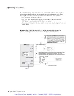
Record Your Systems Configuration
You may wish to record your configuration information in the chart
←
COM port functions set with internal jumpers
and the PORT and DRPCHK commands.
←
RS-485 resistors are selected with internal DIP
switches, or connected externally.
Much of this chart is repeated, along with other facts, on the magnetic information label located
on the side of the ZETA6xxx chassis. You can leave the label on the ZETA6xxx, or you can
remove it and place it in a convenient location near the ZETA6xxx (e.g., on an equipment cabinet
door).
Use a marker or pen to write configuration information in the spaces at the bottom of the label. If
you have multiple ZETA6xxxs, you can remove the labels and stack them on top of each other,
with the bottom edge of each visible. This shows information about all axes at a glance.
Recommended Set-up Elements (software & hardware)
Command
Function
Factory Default Setting
DELVIS
Enable/disable electronic viscosity. Electronic viscosity is automatically
inhibited above 3 rps. (See set-up procedure on page 38.)
DELVISØ
(disabled)
DRPCHK*
Establish the type of check for an RP240. In general, this command is
necessary only if you are using RS-485, which forces the RP240 to be
connected to the
COM 1
connector, instead of being connected to the
COM 2
connector.
DRPCHK3
DWAVEF
Match the motor waveform (required for matching the motor to the
ZETA6xxx).
DWAVEF1
(-4% 3rd harmonic)
ECHO
Enable/disable echoing of characters. If communicating over RS-232 to the
master ZETA6xxx in an RS-485 multi-drop, see setup requirements on page
50.
ECHO1
(enabled; but if using RS-485,
COM 2
is changed to
ECHOØ
by default)
PORT
Identify the COM port to be affected by subsequent serial communication
set-up commands (
DRPCHK
,
E
,
ECHO
,
EOT
,
BOT
,
EOL
,
ERROK
,
ERRBAD
,
ERRDEF
,
XONOFF
, and
ERRLVL
).
PORT1
(
COM 1
is affected)
DACTDP**
Enable/disable active damping. Active damping is automatically inhibited at
or below 3 rps. If active damping is enabled, anti-resonance is automatically
inhibited. (See set-up procedure on page 36.)
NOTE
In most applications, the
factory default settings
are adequate.
Most of the software configuration commands (see table below) are not saved in non-volatile
memory and therefore must be executed every time the ZETA6xxx is powered up or reset.
Therefore, you may wish to include the software configuration commands in the set-up program.
The set-up program is automatically executed when the ZETA6xxx is powered up or reset; in it,
you place the configuration commands that establish the operational readiness you require for
your particular application. A sample set-up program is provided below. For more detailed
information on creating a set-up program, refer to the 6000 Series Programmer’s Guide.
Artisan Technology Group - Quality Instrumentation ... Guaranteed | (888) 88-SOURCE | www.artisantg.com


