background image

LT6488 issue 1 (06/13)


Paragon P6Users Instructions 


SECTION ONE Introduction Continued 


IMPORTANT INFORMATION 


The appliance is for use on Natural Gas (G20 @ 20mbar) only.  


The chimney or flue (unless new or previously used with a gas appliance) shall be swept before 
installation if it has been used for solid fuel. 


Failure to install appliance correctly could lead to prosecution. 
In GB (Great Britain), the appliance must be installed by a competent person i.e. Gas Safe-
registered, in accordance with the GAS SAFETY (INSTALLATION AND USE) REGULATIONS, 
The Building Regulations (or The Building Regulations (Scotland) or The Building Regulations 
(Northern Ireland)) and The Current I.E.E. Wiring Regulations, if appropriate.  
In IE (Ireland), the appliance must be installed by a competent person and installed in accordance 
with the current edition of I.S.813 Domestic Gas Installation, the current Building Regulations and 
the current ETCI rules for electrical installation, if appropriate.   


The  glass  front  of  this  fire  acts  as  a  dress  guard,  conforming  to  BS  1945  (1997)  however;  a 
fireguard  conforming  to  BS6539  (1997)  must  be  used  to  protect  young  children,  the  elderly  or 
infirm.   


The  appliance  MUST NOT be  used  with  the  glass  safety  screen  removed or  if  it  is damaged  or 
cracked. 


During  initial  firing,  an  odour  may  be  evident.  This  is  the  starch  binder  used  during  the 
manufacture of the fibre components of the fire, and there are 

no harmful

 effects produced. 


During the warming up and cooling down of the appliance you may experience some expansion 
and contraction noises. These are normal. 


During the normal operation of the fire some black staining may appear on some parts of the fuel 
bed.  This  is  quite  normal  and  adds  to  the  appearance  of  the  appliance.  However,  if  excessive 
black  staining  does  occur  it  may  be  due  to  the  fuel  bed  being  incorrectly  laid.  This  should  be 
checked prior to contacting a service engineer. 


Due to the nature of the high gloss finish on the outer trim, you may experience some markings in 
the form of a film. This is quite normal and can be wiped off using a dry clean cloth when the fire 
is cold causing no damage to the trim. 

* The top of the outer firebox is not a working surface and therefore you should avoid placing 
items on top* 

Summary of Contents for P6

Page 1: ...NSTRUCTIONS Please read these instructions carefully before you start installing or using this appliance Keep this booklet handy for future reference This appliance is For use in Great Britain or IRELAND only Paragon Fires Charlton Jenrick Ltd TELFORD SHROPSHIRE TF3 3AR ...

Page 2: ...ION INSTRUCTIONS SECTION FIVE Appliance Data 10 SECTION SIX Regulations and Warnings 11 SECTION SEVEN Siting the Appliance Flue Class1 12 Installation Compatibility hole in wall 12 SECTION EIGHT to Install Appliance Checking the Flue and Fire Opening 12 Fitting the closure plate 13 Gas supply routing 13 Mounting the appliance 13 Connect the gas supply 13 Fitting the glass panel 13 SECTION NINE Che...

Page 3: ...otection After handling wash hands and other exposed parts If a vacuum is used for cleaning the coals or cleaning after servicing installation it is recommended that it is of the type fitted with a HEPA filter Disposal of refractory ceramic materials To keep dust to a minimum these materials should be securely wrapped in polythene and be clearly labelled RCF waste These materials are not classifie...

Page 4: ...d conforming to BS 1945 1997 however a fireguard conforming to BS6539 1997 must be used to protect young children the elderly or infirm The appliance MUST NOT be used with the glass safety screen removed or if it is damaged or cracked During initial firing an odour may be evident This is the starch binder used during the manufacture of the fibre components of the fire and there are no harmful effe...

Page 5: ...the battery directly under the spark generator unit The full lighting procedure is as follows a Push slide control lever in as far as possible a clicking noise will be heard and the pilot will light PUSH FIRMLY FOR ABOUT 20 SECONDS b Allow the lever to spring back the pilot light should remain alight and the main burner should light on its low setting c Should the pilot fail to light pull the leve...

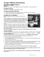
Page 6: ...roblem Note Take care when cleaning in this area so as not to damage the pilot assembly GLASS CLEANING From time to time it will be necessary to clean the glass panel of your 660 PC fire We recommend you use a Ceramic hob cleaner these are available for all leading super markets i e ASDA TESCO SAINSBURY S Etc Brands of hob cleaning we have tested and found suitable are HOB BRITE VITRO CLEAN Ensure...

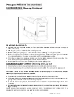
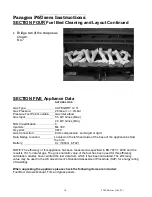
Page 7: ...uts retaining the LH and RH glass panels SECTION FOUR Fuel Bed Cleaning and Layout Use only the fuel bed components provided and no additional parts must added Incorrect positioning of the fuel bed components could result in the staining of the glass panel Important Refer to the Health Safety Notice located on page 3 of this booklet before cleaning or replacing any refractory material The fuel bed...

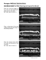
Page 8: ...ed Place four of the log shapes on top of the air tray touching the glass back liner as shown No 12 No 16 No 16 No 14 Place a single layer of the bark chipping along the front edge of the air tray as shown Place four shapes shown within the burner top plate and air tray as shown No 15 No 14 No 15 No 12 ...

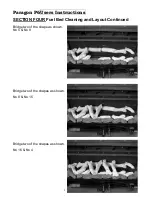
Page 9: ...06 13 Paragon P6Users Instructions SECTION FOUR Fuel Bed Cleaning and Layout Continued Bridge two of the shape as shown No 5 No 8 Bridge two of the shapes as shown No 8 No 15 Bridge two of the shapes as shown No 16 No 4 ...

Page 10: ...ata Badge Location Located on the left hand side of the base of the appliance behind the trim Battery 9 v 1604G 6F22 NOTE The efficiency of this appliance has been measured as specified in BS 7977 1 2009 and the result is 74 1 natural gas The gross calorific value of the fuel has been used for this efficiency calculation Gastec have certified the test data from which it has been calculated The eff...

Page 11: ...y a competent person and installed in accordance with the current edition of I S 813 Domestic Gas Installation the current building regulations and the current ETCI rules for electrical installation if appropriate Prior to the installation ensure that the local distribution conditions identification of type of gas and pressure and adjustment of the appliance are compatible G20 20mbar IMPORTANT NOT...

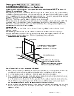
Page 12: ... a maximum opening of 430mm This allows a 10mm overhang The total width of the closure plate is 520mm and will accommodate a maximum opening of 510mm This allows a 10mm overhang PREPARING THE OPENING CHECKING THE FLUE AND FIRE OPENING Check that the chimney conforms to the required specifications as previously stated Examine the condition and carry out any remedial work including removing any debr...

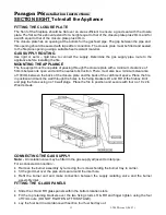
Page 13: ...mum clearance of 50mm between its open end and the nearest obstruction There must also be a minimum clearance of 100mm between the back of the closure plate and the back of the catchment space Place the fire in position and mark the wall through the holes in the fixing brackets LH and RH of the firebox Drill and plug the holes using no 10 wall plugs Place the fire in position and secure with four ...

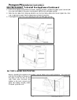
Page 14: ... retaining bracket over the five fixing studs and fit and tighten the 7mm nuts making sure again that the glass panel is flush and central Final tighten the four 7mm nuts retaining the LH and RH glass panels BATTERY CONNECTION POSITION Before operating the appliance the battery must be fitted to the spark generator The generator and boot connection is located on the base of the fire box on the rig...

Page 15: ...nts please use only the specified number of components as illustrated Only use fuel bed component provided for this appliance In the interest of safety and efficiency of your appliance when replacing the fuel bed it is essential that the existing fuel bed be removed and the new components are replaced correctly as a complete set Lay fuel bed as described under Users Section Warning It is important...

Page 16: ...sconnect the fire from the gas supply and seek expert advice Spillage can be caused by a restriction in the flue system down draught or insufficient ventilation into the room where the fire is installed FIT STANDARD FASCIA Offer the decorative fascia up squarely and centrally The back face of the fascia will have cut out to give clearance for glass retaining brackets Use these slots as a guide sli...

Page 17: ...be used to protect young children the elderly or infirm The curing effect of heating the logs and other refractory components will cause an initial odour This is due to the starch used in the manufacturing process and is non toxic Any debris should be cleaned from the appliance A vacuum cleaner can be used but only after all the loose logs have been removed The appliance should be serviced annuall...

Page 18: ...from the inlet elbow Remove the operating lever assembly Remove the loose fuel bed components Lift off the decorative fascia Remove the battery from the boot lead and remove the two fixing screws attaching the spark generator to the fire box body Remove the four screws attaching the burner tray to the fire box shelf Pull carefully forward and remove the complete tray assembly For normal servicing ...

Page 19: ...t the pilot Carefully pull off the ignition lead Disconnect the thermocouple at the end of the main control valve Remove the cross headed nut holding the pilot to the chassis Carefully remove the oxy pilot Re assemble in reverse order REPLACEMENT OF THE SPARK GENERATOR Disconnect leads from control unit Re assemble in reverse order FLUE CHECK Remove the fire from the opening Reversing fitting inst...

Page 20: ...t be installed by a Gas Safe registered person 2 The appliance must be used in accordance with the user s instructions 3 The appliance must be serviced annually by a Gas Safe registered person 4 The service log must be correctly filled out and the record of annual services must be up to date and supported by receipts in each case 5 This warranty is not transferable and relates to the original inst...

Page 21: ...the helpdesk Model Paragon P6 Serial No This information can be found on the label attached to the packaging and on the data badge which is located on the left hand side of the base of the appliance behind trim Retailer Name ___________________________________________ Address ________________________________ ___________________________________________ ___________________________________________ Da...

Page 22: ...ate of First annual service Engineer Name Gas Safe Registration No Date of Second annual service Engineer Name Gas Safe Registration No Date of Third annual service Engineer Name Gas Safe Registration No Date of Fourth annual service Engineer Name Gas Safe Registration No We may introduce modifications to products from time to time and consequently the details given in this booklet are subject to ...

Page 23: ...TAILS Name ________________________________ Address ________________________________ Post Code TELEPHONE No PRODUCT DETAILS Model Paragon P6 Serial No Date of Purchase This information can be found on the label attached to the packaging and on the data badge which is located on the left hand side of the base of the appliance behind trim WHERE DID YOU PURCHASE THIS PRODUCT Name ____________________...

Page 24: ... Restrictor Label Air Tray Part No 6081 Glass Panels 2 x side 1 x Front Log Fuel Bed 6343 9v Battery 1904 Control Knob Kit Bagged 6291 Spare Fixings A 0411 Closure plate Outer Fascia Data Badge Warning Label 1409 ID Label Packing Labels Grommet 1092 7mm Nut Spinner Beige chippings 46g Part No 6461 Serial Number Inspector ...

Reviews: