


14
IMPORTANT !
• Use only the double-shielded cable supplied with the camera. The interface between the camera and control
unit is proprietary, and NOT SCSI! Use of other cables may damage the system!
• NEVER connect anything except the camera to the DB-25 connector on the control unit.
• Do not use cable extenders to create a longer cable, as power losses and data corruption will occur. In
addition to the 5 meter (15 feet) cable supplied with the camera, an 8 meter (25 feet) cable is available from
Panoscan.
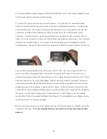
• We recommend that you leave the processor in the storage case to avoid accidental falls which could destroy
the hard drive or corrupt images stored on the hard drive. Otherwise make sure the unit is being used in a
“safe” position.
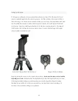
5.
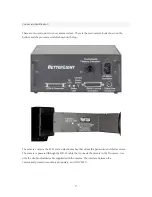
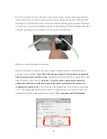
Next you need to connect the processor to the host computer. The camera control unit has a
single SCSI-2 50-pin High Density shielded connector, which is always internally terminated with
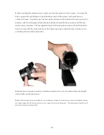
active termination. In most cases you will be using the Processor with the FireWire converter
provided by Panoscan. Begin by connecting the SCSI connector to the processor, always being
careful to mate the connector squarely and firmly into its fully locked position. Avoid stress on this
connector, which might damage the locking tabs or cause poor connections.
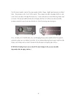
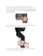
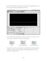
6.
Next plug the other
end of the SCSI DB25 connection into the SCSI converter and secure the connection with the two
screws.
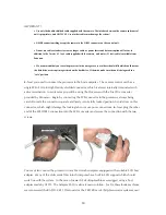
You may also connect the processor to any Macintosh computer equipped with a suitable SCSI host
adapter. Many of the older model Macintosh computer have built in SCSI support which should
work fine with the system. In the case of newer G4 desktop machines we suggest using a host
adapter made by ATTO. The Adaptec 2930 is also a known solution. For G4 Powerbook machines
we recommend the RATOC CB31 Pismo card or the CB32PB cards. (http://www.ratocsystems.com/)
Summary of Contents for MARK TWO
Page 1: ...PANOSCAN MARK TWO OPERATION MANUAL V1 1 ...
Page 37: ...37 ...


