BA_PH_UT300_EN_18-21.docx
3
List of Figures
Figure 1: Start Screen .............................................................................................................................. 7
Figure 2: Machine access: no key ............................................................................................................ 8
Figure 3: Machine access: user name ..................................................................................................... 8
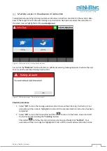
Figure 4: Machine access: Training time exceeded ................................................................................. 9
Figure 5: Warning message "Overdue Instruction"................................................................................. 9
Figure 6: Colored background of the actual values ............................................................................... 10
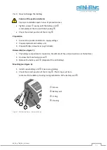
Figure 7: Position indicator - battery change ........................................................................................ 12
Figure 8: Main screen with "Setup menu”
............................................................................................ 13
Figure 9: Setup menu: Password ........................................................................................................... 13
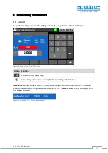
Figure 10: Speed setting for milling cutter ............................................................................................ 14
Figure 11: „Software Limit" in the “speed window”
............................................................................. 14
Figure 12: Effective height (incremental) .............................................................................................. 15
Figure 13: Absolute height .................................................................................................................... 16
Figure 14: Swivel angle for the milling spindle ...................................................................................... 17
Figure 15: Absolute fence ...................................................................................................................... 18
Figure 16: Incremental fence ................................................................................................................ 19
Figure 17: Swivel-away device dialog (example type 320) .................................................................... 20
Figure 18: Main menu of machine parameters ..................................................................................... 21
Figure 19: Tool overview ....................................................................................................................... 22
Figure 20: Creating a tool ...................................................................................................................... 23
Figure 21: Edit an existing tool / select line .......................................................................................... 24
Figure 22: Select the tool for program creation .................................................................................... 25
Figure 23: Empty program list ............................................................................................................... 25
Figure 24: Program settings for tool ..................................................................................................... 26
Figure 25: Program creation: Assign feed rate ...................................................................................... 26
Figure 26: Program list with a stored program ..................................................................................... 27
Figure 27: DIP switch settings ............................................................................................................... 28
Figure 28: Search network for WuT Com servers.................................................................................. 28
Figure 29: Open network parameters ................................................................................................... 29
Figure 30: Set network parameters ....................................................................................................... 29
Figure 31: Server restart ........................................................................................................................ 30
Figure 32: Perform a new scan .............................................................................................................. 30
Figure 33: Log in to Com server ............................................................................................................. 30
Figure 34: Open serial parameters ........................................................................................................ 31
Figure 35: Serial parameter settings 1 .................................................................................................. 31
Figure 36: Serial parameter settings 2 .................................................................................................. 31


