BA_PH_UT300_EN_18-21.docx
11
7
Machine Fences
Different types of fences are used depending on the machine type:
Fence 302 (Machine Type 245/100 and 245/200)
With this type, the total and partial fence must be adjusted manually. For adjustment, two hand
lever screws are loosened, and the fence is adjusted by means of a hand wheel. If the fence has been
positioned at the desired position, the two hand lever screws must be tightened again. The total
fence is equipped with an additional position indicator (see
7.4 below).
Fence 311 (Machine Type 245/100 and 245/200)
With this type, the total fence is automatic, and the partial fence can be adjusted manually. Before
adjusting, both "clamping levers" must be released. Then the total fence can be adjusted automati-
cally resp. the partial fence can be adjusted by means of a handwheel. If the fence has been posi-
tioned at the desired position, the two "clamping levers" must be tightened again.
Fence 320 (Machine Type 245/300)
This fence is completely automated and is controlled by two motors resp. is clamped electro-me-
chanically. For lifting the fence two screws must be loosened manually.
Additional Position Indicator with Fence 302
The fence type 302 is equipped with an additional position indicator. This makes possible to read the
position values not only at the control, but also directly at the total fence.
7.4.1
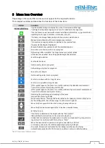
Button functions of the additional indicator
•
When the
key is pressed, the incremental measurement function switches on or off.
With the Auto-ID function, pressing this button accepts the new ID.
•
When the
key is pressed, the calibration starts and acknowledges an existing fault.
•
When the
key is pressed, the parameter level is activated.
•
In the operating mode "Alphanumeric Display", the previously received setpoints (setpoints 1
and 2) are acknowledged with the respective key, depending on the acknowledgement setting.
7.4.2
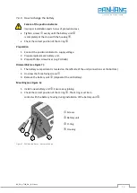
Battery Buffering
The battery enables the measurement of de-energized adjustments. Depending on the duration of
the battery operation (also storage) and the frequency of the de-energized adjustments, the battery
life is approx. 5 years. The battery voltage is checked in a time interval of approx. 5 min. If the battery
voltage falls below a certain value, the battery symbol flashes in the display. If the battery voltage
drops further, the symbol appears permanently. The battery should be changed within approx. three
months of the first appearance of the battery symbol. When changing the battery, it is essential to
observe the instructions in the following section.
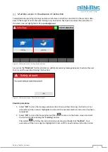
Status Word:
The status word signals the state of charge of the battery. If the charging voltage is critical, bit 11 is
set; if the battery is empty, bit 7 is also set to signal a fault.


