background image

13

English

Connections

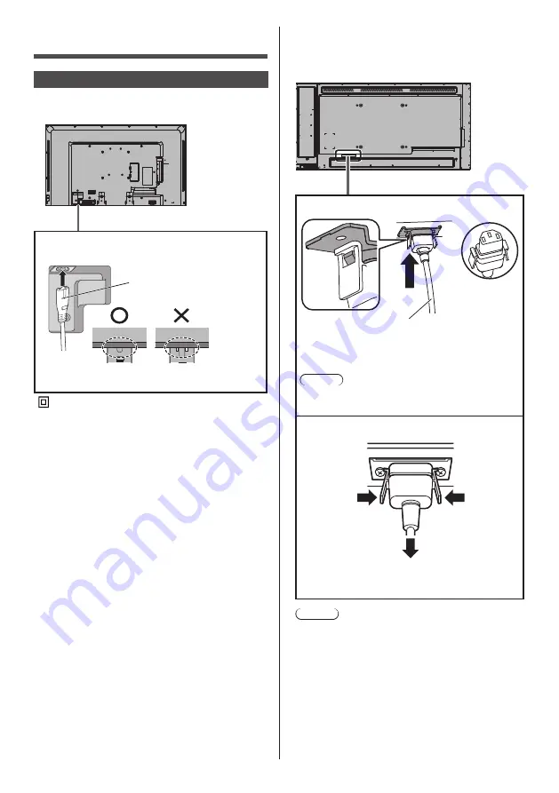
AC cord connection and fixing

43/48/55-inch models

Back of the unit


Insert the AC cord securely all the way seated on 

the back side of the unit.


 Class II equipment.

65-inch model

● 

The AC cord for the 65-inch model has a 3-pin plug 

with earth.

Back of the unit

AC cord fixing

AC cord (supplied)

Plug the connector into the display unit.

Plug the AC cord until it clicks.

Note

● 

Make sure that the AC cord is locked on both the 

left and right sides.

Unplug the AC cord

Unplug the connector pressing the two knobs.

Note

● 

When disconnecting the AC cord, be absolutely 

sure to disconnect the AC cord plug at the socket 

outlet first.

● 

The supplied AC cord set is for this unit exclusive 

use. Do not use this for other purposes.

AC cord (supplied)

Insert the plug until the line is hidden.

Summary of Contents for TH-43LFE8U

Page 1: ...nch model TH 48LFE8U 48 inch model TH 55LFE8U 55 inch model TH 65LFE8U 65 inch model TH 43LFE8E 43 inch model TH 48LFE8E 48 inch model TH 55LFE8E 55 inch model TH 65LFE8E 65 inch model English Please read these instructions before operating your set and retain them for future reference ...

Page 2: ...ay To obtain maximum benefit from your set please read these Instructions before making any adjustments and retain them for future reference Retain your purchase receipt also and note down the model number and serial number of your set in the space provided on the rear cover of these instructions Visit our Panasonic Web Site http panasonic com ...

Page 3: ...t Multi Media Player only 34 Starting ending Media Player 35 Resume Play function 35 On Screen Menu Displays 36 Adjusting Position 38 Auto setup 38 Sound Adjustment 40 Picture Adjustments 41 Picture Profiles 43 Saving profiles 44 Loading profiles 45 Editing profiles 45 Setup menu 47 Signal 47 Screensaver For preventing image retention 50 Input label 51 Power management settings 51 Wobbling 52 No a...

Page 4: ...with dry cloth 7 Do not block any ventilation openings Install in accordance with the manufacturer s instructions 8 Do not install near any heat sources such as radiators heat registers stoves or other apparatus including amplifiers that produce heat 9 Do not defeat the safety purpose of the polarized or grounding type plug A polarized plug has two blades with one wider than the other A grounding ...

Page 5: ...ce that may cause undesired operation CANADIAN NOTICE This Class A digital apparatus complies with Canadian ICES 003 WARNING Not for use in a computer room as defined in the Standard for the Protection of Electronic Computer Data Processing Equipment ANSI NFPA 75 For permanently connected equipment a readily accessible disconnect device shall be incorporated in the building installation wiring For...

Page 6: ...iance keep it away from sources of strong electromagnetic fields WARNING This is a class A product In a domestic environment this product may cause radio interference in which case the user may be required to take adequate measures IMPORTANT THE MOULDED PLUG FOR YOUR SAFETY PLEASE READ THE FOLLOWING TEXT CAREFULLY This display is supplied with a moulded three pin mains plug for your safety and con...

Page 7: ... table cloths and curtains For sufficient ventilation see page 9 Caution For use only with UL Listed Wall Mount Bracket with minimum weight load 36 2kg When installing the Display vertically When installing the Display vertically be sure that the Power Indicator comes to the downside Heat is generated and it may cause fire or damage to the Display Power indicator 43 48 55 inch models 65 inch model...

Page 8: ...n off but it is not a malfunction To prevent the spread of fire keep candles or other open flames away from this product at all times CAUTION If problems or malfunction occur stop using immediately If problems occur unplug the power supply plug Smoke or an abnormal odour come out from the unit No picture appears or no sound is heard occasionally Liquid such as water or foreign objects got inside t...

Page 9: ... install the unit where it is 2 800 m 9 186 ft and higher above sea level Failure to do so may shorten the life of the internal parts and result in malfunctions About space when installing When using the pedestal optional accessory leave a space of 10 cm 3 15 16 or more at the top left and right and 5 cm 1 31 32 or more at the rear and also keep the space between the bottom of the display and the ...

Page 10: ...loth in water to which a small amount of neutral detergent has been added and then wring the cloth dry Use this cloth to wipe the cabinet and then wipe it dry with a dry cloth Do not allow any detergent to come into direct contact with the surface of the Display If water droplets get inside the unit operating problems may result Avoid contact with volatile substances such as insect sprays solvents...

Page 11: ...nsmitter AAA R03 UM4 type 2 Clamper 3 For TH 43LFE8U TH 48LFE8U TH 55LFE8U and TH 65LFE8U Warranty card 1 Power supply cord TH 43LFE8U TH 48LFE8U TH 55LFE8U TH 43LFE8E TH 48LFE8E TH 55LFE8E TH 65LFE8U TH 65LFE8E Attention Store small parts in an appropriate manner and keep them away from young children In case you lost accessories please consult your dealer Dispose the packaging materials appropri...

Page 12: ...rve the following precaution 1 Batteries shall always be replaced as a pair Always use new batteries when replacing the old set 2 Do not combine a used battery with a new one 3 Do not mix battery types example Zinc Carbon with Alkaline 4 Do not attempt to charge short circuit disassemble heat or burn used batteries 5 Battery replacement is necessary when remote control acts sporadically or stops o...

Page 13: ...ng AC cord supplied Plug the connector into the display unit Plug the AC cord until it clicks Note Make sure that the AC cord is locked on both the left and right sides Unplug the AC cord Unplug the connector pressing the two knobs Note When disconnecting the AC cord be absolutely sure to disconnect the AC cord plug at the socket outlet first The supplied AC cord set is for this unit exclusive use...

Page 14: ...clampers as shown below If you need more clampers purchase them from your dealer Available from the customer service Keep pushing both side snaps hole 1 Attach the clamper Insert the clamper in a hole To remove from the unit snaps Keep pushing the knob hooks 2 Bundle the cables Set the tip in the hooks To loosen knob ...

Page 15: ...5V 1A to an external device when receiving images see page 22 31 8 IR IN IR OUT Infrared Signal Input output Terminal Use this when operating more than one display with one remote control see page 21 9 AUDIO IN Audio input terminal shared with DVI D IN and PC IN see page 17 18 10 AUDIO OUT Analogue Audio Output Terminal Connect to audio equipment with analogue audio input terminal see page 21 Note...

Page 16: ...re HDMI cable not supplied Video Cassette Recorder DVD Player Pin assignments and signal names for HDMI Terminal Pin No Signal name T M D S Data2 T M D S Data2 Shield T M D S Data2 T M D S Data1 T M D S Data1 Shield T M D S Data1 T M D S Data0 T M D S Data0 Shield T M D S Data0 T M D S Clock T M D S Clock Shield T M D S Clock CEC SCL SDA DDC CEC Ground 5V DC Hot Plug Detect ...

Page 17: ...ed with PC IN DVI D video cable Within 5 m not supplied Stereo mini plug M3 cable not supplied PC with DVI D video out Pin assignments and signal names for DVI D Input Connector Pin No Signal Name T M D S data 2 T M D S data 2 T M D S data 2 shield DDC clock DDC data T M D S data 1 T M D S data 1 T M D S data 1 shield 5 V DC GND Ground Hot plug detect T M D S data 0 T M D S data 0 T M D S data 0 s...

Page 18: ...ine detail with sufficient clarity In ENGLISH US OSD language 16 9 is displayed as FULL Note The PC IN terminal is DDC2B compatible If the computer being connected is not DDC2B compatible you will need to make setting changes to the computer at the time of connection Some PC models cannot be connected to the set There is no need to use an adapter for computers with DOS V compatible Mini D sub 15P ...

Page 19: ...Ground Audio R Red SERIAL terminal connection The SERIAL terminal conforms to the RS 232C interface specification so that the Display can be controlled by a computer which is connected to this terminal Male Female D sub 9p RS 232C Straight cable not supplied COMPUTER etc Note Use the RS 232C straight cable to connect the computer to the Display The computer shown is for example purposes only Addit...

Page 20: ...he parameter signal does not need to be sent STX C1 C2 C3 P1 P2 P3 P4 P5 ETX Start 02h 3 character command 3 bytes Colon Parameter s End 03h Command Command Parameter Control details PON None Power ON POF None Power OFF AVL Volume 000 100 AMT 0 Audio MUTE OFF 1 Audio MUTE ON IMS None Input select toggle HM1 HDMI 1 input HDMI1 HM2 HDMI 2 input HDMI2 DV1 DVI D IN input DVI D PC1 PC IN input PC VD1 V...

Page 21: ... display does not operate Repeating the above connections enables the daisy chain connection Note Connection cables are not supplied with this unit Mini plug M3 cable commercially available First display Second display Third display AUDIO OUT terminal connection line in Stereophonic sound code not supplied Audio equipment Note Audio equipment and the cable shown are not supplied with this set To o...

Page 22: ...n receiving images If the electric current exceeding the power supplying capability is applied the output is blocked and the following message is displayed USB DC5V OUT overload Please remove cable or equipment then turn the display off on In this case remove the equipment and then turn the power off on using the remote control etc Note If the direct connection to this unit is not possible due to ...

Page 23: ...age 55 Orange Red Green Power OFF with Power management function Orange Red Green Power management function see page 51 When the power of the unit is OFF Main Power On Off switch OFF No light Note The unit will still consume some power as long as the power cord is still inserted into the wall outlet When the power indicator is orange power consumption during standby is generally larger than that o...

Page 24: ...he position size of the screen see page 38 11 INPUT Switches input to display on the screen see page 27 12 PICTURE see page 41 13 SOUND see page 40 14 RECALL Displays the current setting status of Input mode Aspect mode etc see page 27 15 RETURN Used to return to the previous menu see page 36 16 FUNCTION see page 57 17 OFF TIMER Switches to stand by after a fixed period see page 28 18 Numeric butt...

Page 25: ...ee page 13 2 Connect the plug to the socket outlet Note Main plug types vary between countries The power plug shown at left may therefore not be the type fitted to your set When disconnecting the AC cord be absolutely sure to disconnect the AC cord plug at the socket outlet first 3 Press the Main Power On Off switch on the unit to turn the set on Power On Power Indicator Green Picture is displayed...

Page 26: ...the unit next time After the setting the items can be changed in the following menus OSD language see page 52 Date and time see page 54 Display orientation see page 58 Power ON message The following message may be displayed when turning the unit power ON No activity power off Precautions No activity power off is enabled When No activity power off in the Setup menu is set to Enable a warning messag...

Page 27: ...see page 60 Image retention image lag may occur on the LCD display panel when a still picture is kept on the panel for an extended period To prevent such a problem using the screensaver and wobbling is recommended see page 50 52 RECALL It is possible to check the setting status of input label picture mode etc Press RECALL Current setting status will be displayed 16 9 Off timer 90 min Memory name M...

Page 28: ...Press MUTE appears on the screen and the sound is muted Press again to reactivate the sound It is also reactivated when the power is turned on off or the volume level is changed While MUTE is active is displayed as a reminder after operation In ENGLISH US OSD language is displayed as MUTE OFF TIMER The Display can be preset to switch to stand by after a fixed period 30 min 60 min 90 min The settin...

Page 29: ...els Aspect mode Description Zoom1 Letterbox pictures with a 16 9 aspect ratio are enlarged vertically to fill the screen The top and bottom edges of the pictures are cut off Zoom2 Letterbox pictures with a 16 9 aspect ratio are enlarged vertically and horizontally to fill the screen The top and bottom edges as well as the left and right edges of the pictures are cut off Note Do not allow the pictu...

Page 30: ...ain 4 Exit the digital zoom mode Press RETURN to exit the mode The screen returns to the previous state just before entering the digital zoom mode and the digital zoom operation guide display disappears Press any of the following buttons to exit the mode Then the operation of the pressed button is performed Remote Control AUTO SETUP POSITION PICTURE INPUT SETUP SOUND DEFAULT RECALL MUTE ASPECT OFF...

Page 31: ... than those formatted in FAT16 or FAT32 cannot be used Up to 32 GB of USB memory in size are supported Only single partition configuration is supported Preparation Prepare the following files in the USB memory for the media player Play file Scenario as necessary File list as necessary Play file The unit s Media Player supports the formats below File name Extension Still image JPG JPEG JPE Moving i...

Page 32: ...laying back large sized files if you set the playing back duration short it may not be played back properly for example noise appears on the screen In that case set the playing back duration longer 10 seconds or longer Group ID for Multi Media Player It is an ID used for grouping on a network during Multi Media Player conditions GroupID Gxx Group xx The xx portion can be set from 01 to 10 Enter a ...

Page 33: ...e following contents will be played on repeat loop 1 Introduction jpg 10 seconds 2 Contents_Video1 wmv 10 seconds 3 Contents_Video2 wmv 20 seconds 4 Contents_Video3 wmv Played for the duration of the play time of the file Multi Media Player Files will be played in the order they were listed in the scenario for Master Scenario and file list Master side Scenario Enter File definition Play time File ...

Page 34: ...r in writing scenario dat filelist dat 4 The play file format is not supported 5 No play file exists 6 It is Multi Media Player but no group ID is specified yet 7 There are several identical file definitions 8 The play time is outside the range 9 The file listed in the scenario is not in the file list 10 The scenario contains 0 or over 1000 play files 11 There are 0 or over 1000 play files Single ...

Page 35: ...ry USB terminal 2 Run a USB memory contents check 3 Change INPUT to USB Ending Change INPUT to other than USB For Multi Media Player Start 1 Connect several units with LAN cables see page 34 Example of setting up LAN connection and IP address Subnet mask 2 Insert USB memory for Media Player into each Display 3 Executes USB memory contents check on each Display 4 Change INPUT for Slave to USB 5 Cha...

Page 36: ... Press Press to select Example Picture menu 50 50 50 50 50 50 5 Picture Default Default Picture mode Normal 2 2 9300K Backlight Contrast Brightness Colour Hue Sharpness Gamma Colour temperature Dynamic contrast Colour enhancement Memory save Memory load Memory edit Off Submenu Press ENTER to display the submenu 3 Set MENU ENTER INPUT Press Press to select 4 Exit from the menu Press Press RETURN to...

Page 37: ...50 50 50 50 50 50 5 Picture Default Default Picture mode Normal Backlight Brightness Colour Hue Sharpness Gamma 2 2 9300K Colour enhancement Memory save Memory load Memory edit Off see page 41 46 Setup menu 1 2 Setup Screensaver Signal Input label Power management settings Wobbling No activity power off OSD language Off Disable English UK 2 2 20 Setup Set up timer Multi Display Settings Date and t...

Page 38: ...e displaying the picture of the corresponding signal select Auto setup and press ENTER Using Remote Control Press AUTO SETUP When Auto Setup does not work Invalid is displayed Auto mode When the PC auto setting is set to On in the Options menu see page 61 automatic position adjustment starts When the display power is turned ON When the input signal is switched Note When the dot clock frequency of ...

Page 39: ...is displayed If this happens adjust so that any such noise is minimized Over scan Turn image over scan On Off Applicable input signal 525i 525p 625i 625p 750 60p 750 50p Component Video RGB DVI D HDMI On Off Note When Off is set H size and V size cannot be adjusted 1 1 pixel mode Adjusts the display size when 1125i or 1125p signal is input Off On Applicable input signal 1125 50i 60i 24PsF 24p 25p ...

Page 40: ...n Default is selected then the settings will be set to factory settings Output select Select the audio output SPEAKERS Internal speakers AUDIO OUT AUDIO OUT terminal output When AUDIO OUT is selected the other menus are greyed out and cannot be selected Audio volume setting is memorized separately for each output Sound mode Normal Emits the original sound Dynamic Accentuates sharp sound Clear Atte...

Page 41: ...htness Colour Hue Sharpness Dynamic contrast Colour enhancement Picture mode This menu switches to easy to see pictures suitable to the picture source or environment where this unit is used Normal For viewing in standard evening lighting environments Dynamic For viewing in brighter environments Cinema For use in viewing tone focused pictures with brightness reduced The setting are memorised separa...

Page 42: ...th and press ENTER Adjust colour temperature Overwrite colour temperature USER1 Yes No 4 Set each item on detail settings screen 150 255 64 0 0 0 Adjust colour temperature USER1 R gain G gain B gain R bias G bias B bias R gain Adjusts the white balance for light red areas 0 to 255 G gain Adjusts the white balance for light green areas 0 to 255 B gain Adjusts the white balance for light blue areas ...

Page 43: ...ement Memory save Memory load Memory edit Off Memory save see page 44 Memory load see page 45 Memory edit see page 45 1 2 3 MEMORY1 MEMORY2 MEMORY3 4 MEMORY4 5 MEMORY5 6 MEMORY6 7 MEMORY7 8 MEMORY8 Overview of Picture Profiles Original picture Adjust picture see page 41 42 Custom picture Example Save the picture adjustment values in the MEMORY1 profile Memory save Original picture Example Load MEM...

Page 44: ...MORY7 8 MEMORY8 Memory save appears for a profile in which the picture adjustments have already been saved 4 Select Ok with and press ENTER Memory save Save the adjusted value in MEMORY1 Ok Cancel 5 Enter a profile name with Entering characters see page 74 MEMORY1 0 1 2 3 4 5 6 7 8 9 a a A b c d e f g h i j k l m n o p q r s t u v w x y z _ Ok Cancel All delete Delete 6 When you finished entering ...

Page 45: ...re stored in memory according to the selected input terminal Editing profiles Delete or rename profiles as follows Deleting profiles 1 In the Picture menu select Memory edit with and press ENTER Memory save Memory load Memory edit 2 Select Memory delete with and press ENTER Memory edit Memory delete Memory name change 3 Select the profile to delete with and press ENTER 1 2 3 MEMORY1 MEMORY2 MEMORY...

Page 46: ...age 74 0 1 2 3 4 5 6 7 8 9 a b c d e f g h i j k l m n o p q r s t u v w x y z _ MEMORY1 a A Ok Cancel All delete Delete 5 When you finished entering the profile name select Ok with and press ENTER a A Ok Cancel All delete Delete To cancel renaming the profile select Cancel ...

Page 47: ...oise reduction FRAME CREATION V freq H freq Dot clock freq Signal format Off YUV Auto Full 0 255 Off Off For DVI Signal 60 00 Hz 74 18 MHz 1125 1080 60i 33 72 kHz Signal YUV RGB in select Cinema reality MPEG noise reduction Signal range Noise reduction FRAME CREATION H freq V freq Dot clock freq Signal format YUV Off Off Full 0 255 Auto Off For PC Signal 60 00 Hz 74 18 MHz 1125 1080 60i 33 72 kHz ...

Page 48: ...signal on the Video HD VD signal which is input from the HD VD connector Cinema reality Faithfully reproduces videos shot with cinema films Set this to Off normally Note In ENGLISH US OSD language Cinema reality is displayed as 3 2 PULLDOWN If Cinema reality is set to On videos including movies shot at 24 frames per second are reproduced more naturally If the video is unnatural with On set set it ...

Page 49: ...g to the signal method during the composite video signal input Set this to Auto normally This automatically detects the input signal format Auto PAL SECAM NTSC NTSC 4 43 PAL M PAL N Set this to Auto when viewing PAL 60 videos When images are unstable When the system is set to Auto images become unstable in rare case under the condition that the input signals are at low level or have many noises In...

Page 50: ...o change the time by 1 minute Keep pressing down to change the time by 15 minutes Screensaver Start 10 00 2015 01 01 THURSDAY Mode Interval Periodic time Operating time 0 00 0 00 Periodic time Deactivated Operating time Note It is not possible to set the duration of Operating time longer than that of Periodic time To set start and finish time of Screensaver Select Time designation in Mode Set Star...

Page 51: ... values are set to the menu of power consumption reduction Individual setting is not available No signal power off Enable HDMI1 power management On HDMI2 power management On DVI D power management On PC power management On Power save On Power management mode Custom The menu of the power consumption reduction is individually set This setting is enabled when Power management mode is set to Custom No...

Page 52: ...te On Backlight brightness is reduced Note If Input search is set to items other than Off the Input search function is prioritised The power management function does not operate for each terminal For details of Input search function see page 59 Wobbling Automatically shifts the display image therefore unnoticeable to the eye to prevent image retention of sharper contour of image Setting this to On...

Page 53: ...ided when enlarged On The display is divided when enlarged When On is set the display aspect is 16 9 Horizontal scale Set the horizontal scale in the multi display 1 5 Vertical scale Set the vertical scale in the multi display 1 5 e g Horizontal scale 5 and Vertical scale 5 is set in the multi display Bezel H adjustment Bezel V adjustment Adjust the area of image hidden in the joint horizontally a...

Page 54: ...ressing once changes time 1 minute Pressing continuously changes time by 15 minutes 6 Set the input Date and time Set date and time shows no programme is set Date and time Set THURSDAY 10 00 2015 01 01 Year 2015 Month Day Hour 1 1 10 0 Set date and time Select Year Month Day Hour Minute Set the selected item Date and time Set THURSDAY 10 00 2015 01 01 Year 2016 Month Day Hour 1 1 10 0 Select Set a...

Page 55: ... press ENTER When Off is selected IP address and other settings can be set manually DHCP DHCP client function On Obtains an IP address automatically when a DHCP server exists in the network the Display is going to be connected Off When a DHCP server does not exist in the network the Display is going to be connected set IP address Subnet mask and Gateway manually IP address IP address display and s...

Page 56: ...devices connected to the network For details of Crestron Connected refer to the Crestron Electronics Inc website Provided only in English http www crestron com For the download of RoomView Express refer to the Crestron Electronics Inc website Provided only in English http www crestron com getroomview Reset You can reset the network setting to the factory default of the Display Select Yes with and ...

Page 57: ...utton mutes the audio and pictures To cancel press any button on the remote control except Standby ON OFF button Shipping condition The following functions are assigned to the numeric buttons as factory default Input Memory load Shortcut 1 HDMI1 MEMORY1 Signal 2 HDMI2 MEMORY2 Screensaver 3 DVI D MEMORY3 Set up timer 4 PC MEMORY4 Power management settings 5 VIDEO MEMORY5 Network settings 6 USB MEMO...

Page 58: ...or Note In the portrait setting the power indicator shall come to the downside OSD position Sets the display position of the on screen menu Each time or is pressed the display position of the on screen menu changes Display example Upper Left 18 00 Centre Centre 18 00 Menu display duration Sets the display duration time for the on screen menu 5 sec 180 sec Menu transparency Sets the transparency ra...

Page 59: ...to display the Options menu The control panel buttons on the main unit cannot be used to display the menu Press RETURN to return to the previous menu The serial number of this device is displayed when Display serial number is selected in step 3 The software License is displayed when Software licenses is selected in step 3 Input search When a signal is not detected another input with a signal is au...

Page 60: ... volume setting before opening the Options menu if you adjust the volume when Initial VOL level is On and cursor is on the menu To adjust sound volume level Press VOL VOL Note When Maximum VOL level is On the volume can only be adjusted between 0 and your maximum range see page 60 Maximum VOL level Adjusts the maximum volume Off The sound volume level can be set up to 100 maximum On The sound volu...

Page 61: ...uted from the Position menu On Other than remote control or menu operation automatic position adjustment starts When the display power is turned ON When the input signal is switched Off timer function Enables disables Off timer function Enable Enables the Off timer function Disable Disables the Off timer function Note When Disable is set the Off timer is cancelled Initial power mode Sets the power...

Page 62: ...item with Select the set point with Information timing No signal warning No signal warning timing No signal error No signal error timing On 5min On 10min No signal warning When set to On the display sends out the no signal warning No signal warning timing Set up the detecting time for no signal warning Range 01 60 Interval 1 minute No signal error When set to On the display sends out the no signal...

Page 63: ...ets to show hide No activity power off precautions at the time the unit is turned on On The warning precautions are shown at the time of power ON Off The warning precautions are not shown at the time of power ON Note This setting is enabled only when No activity power off is Enable see page 52 Power on message Power management Whether to show hide an information message that tells the power has be...

Page 64: ...ng the LAN adapter About Web Browser Web Browser is necessary to use WEB control Compatible OS Windows XP Windows Vista Windows 7 Windows 8 Mac OS X v10 4 v10 5 v10 6 OS X v10 7 v10 8 Compatible Web Browser Internet Explorer 7 0 8 0 9 0 10 0 Safari 4 x 5 x 6 x Mac OS Example of network connection Note To use the network function set each item in Network settings and make sure to set Network contro...

Page 65: ...I1 32 HDMI 2 input HDMI2 33 DVI D IN input DVI D 41 USB input USB Command Control AVMT Shutter control 10 Picture On picture mute deactivated 11 Picture Off picture on mute 20 Audio On audio mute deactivated 21 Audio Off audio on mute 30 Shutter mode Off picture and audio mute deactivated 31 Shutter mode On picture and audio on mute AVMT Shutter control query 11 Picture Off picture on mute 21 Audi...

Page 66: ...d gives advance warning by detecting a predicted abnormality The maximum number of devices that can be registered to monitor differs according to the type of license Up to 2048 devices can be registered and used for free for a maximum of 90 days after the installation to PC has completed For more details visit the following web site http panasonic net prodisplays products et swa100 index html Mult...

Page 67: ...Level button Macintosh Disable proxy server settings 1 From the Safari menu click Preferences General screen is displayed 2 From the Advanced tab click the Change Settings button next to Proxies Click Proxies and set up a proxy server 3 Deselect the Web Proxy and Automatic Proxy Configuration boxes 4 Click Apply Now Enable JavaScript 1 Display Security of Safari 2 Select Enable JavaScript under We...

Page 68: ...splays the type of Display Displays the firmware version of the Display main unit Network status page Click Status then Network status to display the Status information page Displays the current configuration information of the network Displays the configuration details of wired LAN Basic control page To move from another page click Display control then Basic control Power On Off control Use these...

Page 69: ... mode A user can change password only 1 2 3 4 Current password input field New password input field New password input field re enter for confirmation Button for executing password change Note Up to 16 alphanumeric characters can be used for a password When changing the administrator account both Current user name and Current password are required Network config page When connecting by logging in ...

Page 70: ...etting of LAN while connected with LAN might disconnect the connection Adjust clock page Click Detailed set up then Adjust clock to display the Adjust clock page New date field New time field Button to update time and date settings Note Date and time is displayed as when they are not set When Network control is set to On and it is in standby mode date and time display will be blank and they cannot...

Page 71: ...ol the Display using Crestron Connected When you click Crestron Connected the Crestron Connected operation page is displayed If Adobe Flash Player is not installed in your computer or if the browser does not support Flash this page does not appear In this case return to the previous page by clicking Back in the operation page Operation page Tools Info Help Switches the pages for tools information ...

Page 72: ...ultGateway Displays the value in the current setting Exit Return to the operation page Note When you monitor or control the Display using Crestron Connected set Crestron Connected to On in the Network Settings menu Info page Click Info on the operation page Display Name Displays the name of the Display Mac Address Displays the MAC address Resolution Displays the resolution of the Display Power Sta...

Page 73: ...3 Pointing the remote control at the Display you want to control press ID SET 0 ID set Display ID Controller ID 4 Press one of 0 9 Sets the tens digit 5 Press one of 0 9 Sets the units digit The steps from 3 to 5 need to be done within 5 seconds Adjustable ID number range is 0 100 Example To set the ID to 1 After step 3 press 0 and then 1 To set the ID to 12 After step 3 press 1 and then 2 To set ...

Page 74: ... e f g h i j k l m n o p q r s t u v w x y z _ Ok Cancel All delete Delete Switches the keyboard to the upper case alphabet Each time ENTER is pressed the keyboard is switched in the order of lower case upper case and symbols 3 Select M with and press ENTER M Repeat this process to enter the next character 4 Select Space key with and press ENTER MY 0 1 2 3 4 5 6 7 8 9 a a A b c d e f g h i j k l m...

Page 75: ...1 920 1 080 33 8 30 0 74 3 R Y D H 1 125 1 080 60p 1 920 1 080 67 5 60 0 148 5 R Y D H 1 125 1 080 50p 1 920 1 080 56 3 50 0 148 5 R Y D H PC signal Corresponding signal Resolution Dot Scanning frequency Dot clock frequency MHz Format 3 Horizontal kHz Vertical Hz VESA400 640 400 31 5 70 1 25 2 R Y D H 37 9 85 1 31 5 R Y D H VGA 640 480 31 5 59 9 25 2 R Y D H 35 0 66 7 30 2 R Y D H 37 9 72 8 31 5 R...

Page 76: ... 146 3 R Y D H UXGA 1 600 1 200 4 75 0 60 0 162 0 R Y D H 1 920 1 080 1 920 1 080 5 66 6 59 9 138 5 R Y D H 1 920 1 080 67 5 60 0 148 5 R Y D H WUXGA 1 920 1 200 4 74 0 60 0 154 0 R Y D H 1 When 1 125 1 035 60i signal is input it is displayed as 1 125 1 080 60i signal 2 Pixel Repetition signal dot clock frequency 27 0MHz only 3 Signals to represent formats are as follows V Video R D sub RGB Y YCbC...

Page 77: ...reset the settings the adjusted values of the following menus to the factory settings Picture Sound Setup Position Options Remote control 1 Press SETUP to display the Setup menu 2 Select OSD language with and press ENTER for more than 3 seconds The following screen will be displayed Options Display serial number Shipping USB data cloning Software licenses 3 Select Shipping with and press ENTER Shi...

Page 78: ...he input to something other than USB and perform the data cloning Copying the display data to the USB memory 1 Insert the USB memory device to the USB terminal on the side edge of the display USB memory USB terminal Note Depending on the type of a USB memory device it may come in contact with the periphery such as a back cover and cannot be attached Use a commercially sold extension cable or use a...

Page 79: ...message in step 5 is displayed Select USB Memory Display 2 Display Setup menu pressing SETUP 3 Select OSD Language with and press ENTER for over 3 seconds The following display appears Options Display serial number Shipping USB data cloning Software licenses 4 Select USB data cloning with and press ENTER 5 Select USB Memory Display with and press ENTER Select Copy Type Display USB Memory USB Memor...

Page 80: ...l sensor and the remote control If the installation condition is normal pull out the remote control sensor from the edge side of the main unit when using Check whether the remote control designed specifically for use with the unit is being used The unit cannot be operated by any other remote control Check whether the option other than Off is selected in Controller user level in the Options menu se...

Page 81: ...age and audio depending on the type of input signal However this is not a malfunction LCD Display panel Symptoms Check The screen darkens slightly when bright pictures with minimal movements are shown The screen will darken slightly when photos still images of a computer or other pictures with minimal movements are shown for an extended period This is done to reduce image retention on the screen a...

Page 82: ...1 079 mm diagonal 37 0 W 20 8 H 42 5 diagonal 48 inch model 1 054 mm W 592 mm H 1 209 mm diagonal 41 4 W 23 3 H 47 6 diagonal 55 inch model 1 209 mm W 680 mm H 1 387 mm diagonal 47 6 W 26 7 H 54 6 diagonal 65 inch model 1 428 mm W 803 mm H 1 638 mm diagonal 56 2 W 31 6 H 64 5 diagonal No of pixels 2 073 600 1 920 W 1 080 H Dimensions W H D 43 inch model 969 mm 560 mm 61 mm 38 2 22 1 2 4 48 inch mo...

Page 83: ...kHz 0 dB input 10 kΩ load SERIAL IN External Control Terminal D sub 9 Pin RS 232C compatible LAN For RJ45 network connections compatible with PJLink Communication method RJ45 10BASE T 100BASE TX IR IN Mini jack M3 IR OUT Mini jack M3 USB TYPE A USB connector 5V DC 1A USB 3 0 is not supported Sound Speakers 43 48 55 inch models 80 mm 30 mm 2 pcs 65 inch model 96 mm 27 mm 2 pcs Audio Output 20 W 10 ...

Page 84: ...ive to any third party who contacts us at the contact information provided below for a charge no more than our cost of physically performing source code distribution a complete machine readable copy of the corresponding source code covered under GPL V2 0 LGPL V2 1 or the other licenses with the obligation to do so as well as the respective copyright notice thereof Contact Information oss cd reques...

Page 85: ...that used electrical and electronic products and batteries should not be mixed with general household waste For proper treatment recovery and recycling of old products and used batteries please take them to applicable collection points in accordance with your national legislation and the Directives 2002 96 EC and 2006 66 EC By disposing of these products and batteries correctly you will help to sa...

Reviews: