background image

55

ENGLISH

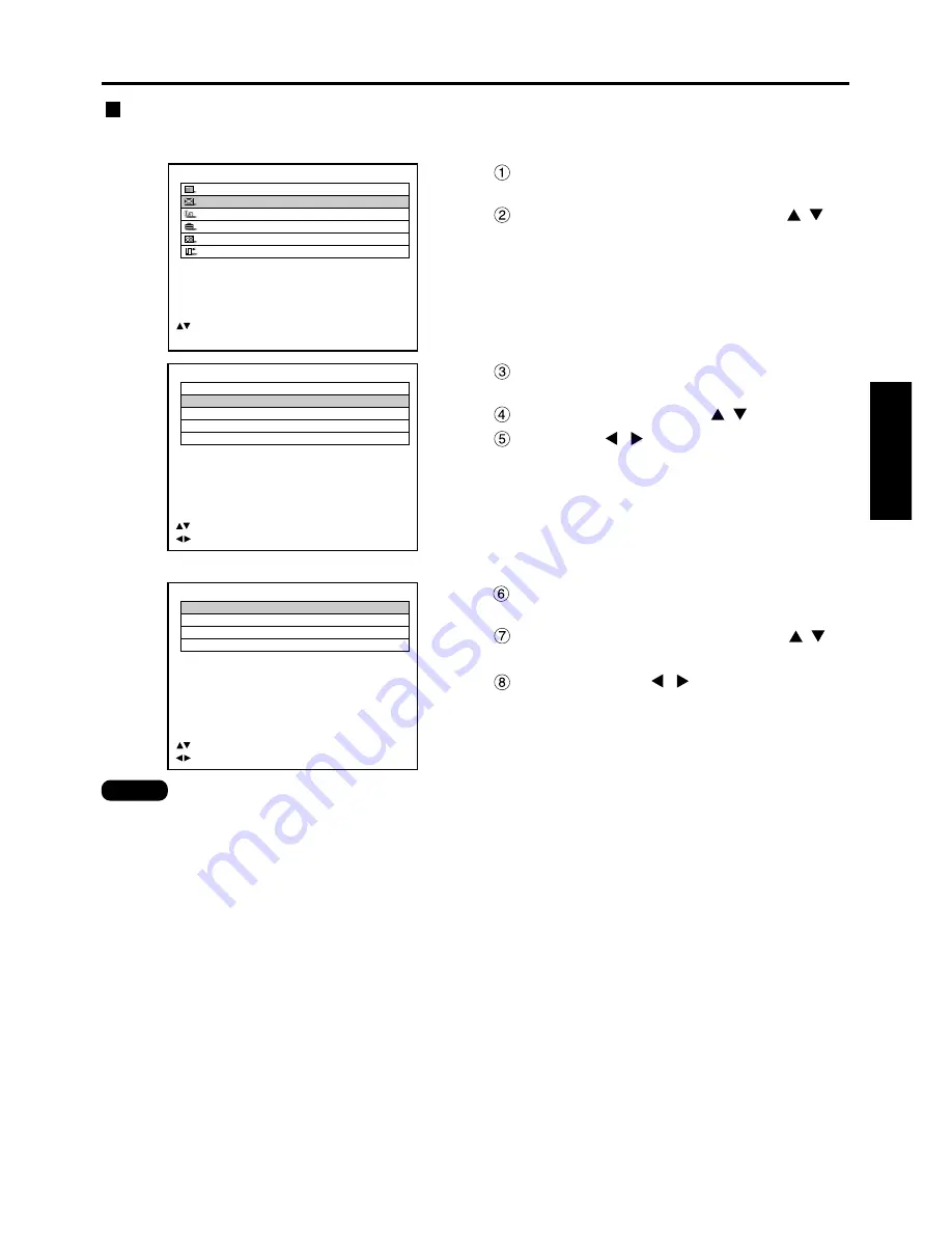
POSITION
  SHIFT
  SIZE

VID AUTO

  BLANKING
  KEYSTONE
  EDGE BLENDING

     :MENU SELECT    
     :CHANGE    ENTER:SUB MENU

Press the “MENU” button.

The MAIN MENU screen will be displayed.

Select the “POSITION” with the 
buttons.

MAIN MENU
         PICTURE
         POSITION
         LANGUAGE
         OPTION
         TEST PATTERN
         SIGNAL LIST

     :MENU SELECT    
ENTER:SUB MENU

Press the “ENTER” button.

The POSITION screen will be displayed.

Select “SIZE” with the 

buttons.

Using the 

buttons, select a size

mode from the following:

“DEFAULT”, “THROUGH”, “ZOOM”, “4:3”, “16:9”,
“S 4:3”, “HV FIT”, “VID AUTO”, “S1 AUTO”, and
“VID AUTO (PRIORITY)”

ZOOM
  INTERLOCKED:

OFF

  V:

  100 %

  H:

  100 %

  HV:

  100 %

     :MENU  SELECT    
     :CHANGE

Press the “ENTER” button.

The SIZE adjustment screen will be displayed.

Select the desired item with the 
buttons.

Adjust with the 

buttons.

Size adjustment

Procedure of adjustment

• For details on the size mode, refer to the next page.
• If “THROUGH” is selected in the size mode, the individual adjustment screen is not displayed.

Note

Summary of Contents for PT-D7500E

Page 1: ...d these instructions completely before operating this unit TQBJ 0114 3 POWER ON OFF RGB 1 RGB 2 AUX MENU STD LENS OSD 1 4 7 2 5 8 3 6 9 0 NEXT USER LIGHT ID ALL ASPECT ID SET Projector Computer Numetric BRIGHT CONTRAST ON SCREEN SYSTEM SEL FUNC 1 D ZOOM ENTER PAGE UP PAGE DOWN VIDEO SHUT S VIDEO FREEZE SHUTTER AUTO SETUP LASER ON OFF ...

Page 2: ...ire or shock hazard do not expose this appliance to rain or moisture Machine Noise Information Ordinance 3 GSGV January 18 1991 The sound pressure level at the operator position is equal or less than 70 dB A according to ISO 7779 WARNING 1 Remove the plug from the wall outlet when this unit is not in use for a prolonged period of time 2 To prevent electric shock do not remove cover No user service...

Page 3: ...of severe electrical shock if the cut off plug is inserted into any 13 amp socket If a new plug is to be fitted please observe the wiring code as shown below If in any doubt please consult a qualified electrician WARNING THIS APPLIANCE MUST BE EARTHED IMPORTANT The wires in this mains lead are coloured in accordance with the following code Green and Yellow Earth Blue Neutral Brown Live As the colo...

Page 4: ...on 45 On screen menus 46 Structure of menu screens 46 Basic operations on menu screen 47 Returning to the previous screen 47 Menu items shown in gray characters 47 Menu items setting 47 Resetting to the factory default 47 Adjusting the picture 48 Switching the picture mode 48 Switching the AI control 48 Adjusting Contrast Bright Color Tint 49 Adjusting the colour temperature 50 Adjusting colour ma...

Page 5: ...ver or modify it in any way High voltages which can cause fire or electric shocks are present inside the projector For any inspection adjustment and repair work please contact an Authorized Service Centre Clean the power cord plug regularly to prevent it from becoming covered in dust If dust builds up on the power cord plug the resulting humidity can damage the insulation which could result in fir...

Page 6: ...ty places or in places where the projector may come into contact with smoke or steam Using the projector under such conditions may result in fire or electric shocks When disconnecting the power cord hold the plug not the cord If the power cord itself is pulled the cord will become damaged and fire short circuits or serious electric shocks may result Always disconnect all cables before moving the p...

Page 7: ...ure It can easily become damaged if struck against hard objects or dropped and injury or malfunctions may result Do not use the old lamp unit The lamp section may break Replacement of the lamp unit should only be carried out after it has completely cooled off otherwise burns may result Disconnect the power cord plug from the wall outlet as a safety precaution before carrying out any cleaning Elect...

Page 8: ...clear images if outside light or the illumination interferes the screen surface Draw window curtains or blinds turn off the lightings near the screen or take other proper measures In rare cases wafture can occur on the screen affected by the warm air from the exhaust port depending on the environment Do not touch the surface of the projection lens with bare hand If fingerprints or stains are left ...

Page 9: ...d with a DVI D input module an optional item can be attached to the projector for computer image viewing Realization of high resolution picture System 2 The optional high or low ceiling mount bracket flexibly fits the projector in individual site conditions System 4 Connection of a signal selector enables to feed a variety of video sources to the projector OFF OFF POWER ON INPUT SELECT 1 2 3 4 5 6...

Page 10: ...s button to enter your menu selection or to run function Standard STD button page 47 Press this button to restore the default factory setting ON SCREEN button page 46 This button turns on and off the on screen indication function SHUTTER button page 45 Press this button to black out the image temporarily Function 1 FUNC1 button page 72 This button can control the functions set in FUNC1 of the Opti...

Page 11: ... O O M A S P E C T POWER ON OFF RGB 1 RGB 2 AUX MENU STD LENS OSD 1 4 7 2 5 8 3 6 9 0 NEXT USER LIGHT ID ALL ASPECT ID SET Projector Computer Numetric BRIGHT CONTRAST ON SCREEN SYSTEM SEL FUNC 1 D ZOOM ENTER PAGE UP PAGE DOWN VIDEO SHUT S VIDEO FREEZE SHUTTER AUTO SETUP LASER ON OFF When the operation mode selector is set to Computer ENTER button Moves the mouse cursor buttons These buttons corres...

Page 12: ... front and rear right and left Remote control receiver window front page 15 This window receives the signal beam emitted from the remote control Projection lens optional Lens for projecting images on the screen Power indicator lamp page 35 The lamp lights in red when the MAIN POWER switch is turned to I on It turns to green when the I button of the remote control or the main unit is pressed LAMP1 ...

Page 13: ... an image automatically corrects the picture positioning on the screen While the auto setup feature is active a message EXECUTING appears on the screen SHUTTER button page 45 Press this button to black out the image temporarily MENU button page 47 Displays and clears the Main Menu It can also return to the previous screen when the menu is displayed Arrow buttons page 47 Use to select an item on th...

Page 14: ...ecessary to supply signals given to the serial input terminal D SUB 9 pin male RGB YPBPR 1 input terminal pages 24 and 25 A terminal to input RGB or YPBPR signals BNC RGB YPBPR 2 input RGB YPBPR 1 output terminal pages 24 25 This terminal active through receives RGB or YPBPR signals or supplies signals given to the RGB1 input terminal D SUB 15 pin female REMOTE2 terminal page 78 The user can remot...

Page 15: ...ont or rear Do not drop the remote control unit Do not expose remote control unit to any liquid Do not use NiCd batteries When the remote control is aimed at the screen the effective control range may be reduced due to the optical loss by screen reflection The remote control may not function properly if an object is in the light path The remote control receiver may not function properly in intense...

Page 16: ...it However if the ID ALL button is pressed the projector can be controlled regardless of the ID number of the projector simultaneous control mode Setting projector ID number to remote control If the ID SET button is pressed the ID number goes back to the one set before pressing the ID SET button unless the NEXT button and a numeric button are pressed within five seconds after the ID SET button is ...

Page 17: ...D EO FR EE ZE SH UT TE R A U T O S E T U P S T D L E N S O S D 1 4 7 2 5 8 3 6 9 0 N E X T U S E R LIG HT ID AL L ID SE T P ro je c to r C o m p u te r Nu m et ric BR IG HT C O N T R A S T O N S C R E E N S Y S TE M S E L FU NC 1 D Z O O M AS PE CT Click button To use the remote control as a mouse please purchase an optional wireless mouse receiver model No ET RMRC1 Note When multiple main units a...

Page 18: ...nely adjusted wit the powered zoom lens and lens shifting mechanism The four leveling feet mounted at the bottom of the projector are level adjustable 0 mm 33 mm which can be used when the floor surface is not horizontal Front Side Leveling feet H SH L L H Side view When optional ceiling mount bracket ET PKD75 Screen unit mm inch 438 558 17 2 21 9 237 9 3 L SW 314 86 140 175 468 117 L1 Top view Sc...

Page 19: ... 20 44 27 29 34 14 40 99 47 84 54 69 68 39 82 09 15 45 17 67 19 90 22 12 26 56 33 23 44 34 55 45 66 56 77 67 88 78 111 00 133 22 1 40 1 61 1 82 2 04 2 46 3 10 4 16 5 22 6 28 Minimum Maximum ET D75LE1 SC 1 87 2 5 1 Minimum Maximum ET D75LE2 SC 2 5 3 75 1 Minimum Maximum ET D75LE3 SC 3 75 6 25 1 Minimum Maximum ET D75LE4 SC 6 25 10 0 1 ET D75LE5 1 0 1 Projection distance L Zoom lens Fixed focus lens...

Page 20: ... 2 0 1 Minimum Maximum ET D75LE2 SC 2 0 3 0 1 Minimum Maximum ET D75LE3 SC 3 0 5 0 1 Minimum Maximum ET D75LE4 SC 5 0 8 0 1 ET D75LE5 0 8 1 Projection distance L Zoom lens Fixed focus lens Effective height SH 70 80 90 100 120 150 200 250 300 350 400 500 600 0 871 0 996 1 120 1 245 1 494 1 868 2 491 3 113 3 736 4 358 4 981 6 226 7 472 1 549 1 771 1 992 2 214 2 657 3 321 4 428 5 535 6 641 7 748 8 85...

Page 21: ... 090 x Screen diagonal inch 0 0963 Maximal distance L 0 0149 x Screen diagonal inch 0 1023 Minimal distance L 0 137 x Screen diagonal inch 0 1146 Maximal distance L 0 2222 x Screen diagonal inch 0 1023 4 3 ET D75LE4 ET D75LE4SC 6 25 10 0 1 16 9 4 3 Zoom lens Fixed focus lens 16 9 5 4 16 9 5 4 16 9 5 4 16 9 5 4 Zoom lens Fixed focus lens Model number of projection lens Aspect ratio Projection dista...

Page 22: ...is case a time base corrector TBC must be connected The projector accepts the following signals video S Video analog RGB and optional input module Some PC models cannot be connected to the projector The pin out and signal names of the S VIDEO IN terminal are shown in the diagram below The pin out and signal names of the RGB2 input terminal are shown in the diagram below Outside view Pin No Ground ...

Page 23: ...ted to PR terminal Blue connected to PB terminal Green connected to Y terminal Video deck TBC built in Example of connecting with VIDEO devices When connecting with a video deck be sure to use the one with a built in time base corrector TBC or use a TBC between the projector and the video deck If nonstandard burst signals are connected the image may be distorted If this is the case connect a TBC b...

Page 24: ...hen stacking projectors using RGB YPBPR YCBCR signals divide the signals at the signal source and use RGB1 input for both projectors When the RGB1 OUT is connected to the external RGB monitor the image quality will be almost the same as that of checking monitors Note Attention For the specifications of the RGB signals that can be applied from the PC see the data sheet on page 99 If your PC has the...

Page 25: ... OFF Signal Selector TW SWS Color monitor with RGB input terminal Digital broadcasting tuner DVD player Signal selector Option Video deck TBC built in Notebook computer Control PC When stacking projectors using RGB YPBPR YCbCr signals divide the signals at the signal source and use RGB1 input for both projectors When the RGB1 OUT is connected to the external RGB monitor the image quality will be a...

Page 26: ...ite SYNC not supported For separate SYNC 75 Ω 0 6 V p p 4 0 V p p For 1 k Ω TTL level Signals supporting analog RGB input modules fH 15kHz 100kHz fV 24Hz 120Hz Dot clock frequency 20 MHz 162 MHz Signals supporting color difference input Types Supported 480i 576i 480p 720 60p 1080 60i 1035 60i 1080 50i 1080 30p 1080 25p 1080 24p 1080 24sF Video Y 1 0 V p p C 0 286 V p p Cr Cb 0 7 V p p Impedance 75...

Page 27: ...Slot cover Remove 2 screws Insert the input module Input module Slot Fix the input module Register the input signal Tighten the two screws This projector needs to register the type of input signal after the installation of the input module For details on the registration of the input signals refer to pages 43 and 46 ...

Page 28: ...be used individually according to the input terminal on the signal selector Digital signals cannot be connected to the signal selector RGB signal input module ET MD95RGB I F Input Input Input Output RS 232C Output RGB signal Component signal Video signal input module ET MD95VM2 Serial digital input module ET MD95SD1 Component signal SD signal Projector RS 232C input terminal Signal selector High v...

Page 29: ...rt the three value synchronizing input to the H H V and V terminals Do not supply synchronizing input signals to H H V and V terminals when supplying SYNC ON GREEN signals Attention Please purchase commercially available interface 2 Connecting the component signals PR Cr Y PB Cb PR Cr Y PB Cb High vision video deck R PR G Y B PB H HÆV V DVD player BS digital HD tuner RGB signal input module option...

Page 30: ...LINE and Y C input Example Each time AUX button is pressed LINE input Y C input The above cycle is repeated When connecting with a video deck be sure to use the one with built in TBC time base corrector or use the time base corrector between the projector and the video deck If burst signals are connected to the nonstandard signals the image may be distorted If this is the case connect the time bas...

Page 31: ...ection for switching the signals of ET MD95VM2 optional on page 65 Insert the input module suitable for the input signal specifications Use the SYSTEM SELECTOR button to toggle the systems of the input module that supports two types of signal specifications Upon toggling the input signals are displayed on the screen and cleared automatically SD signal SD signal output active through Serial digital...

Page 32: ...tton Use a 3C2W or superior cable for connection to transmit the image information without error Example 3C2W 3CFB 4CFB 5C2W 5CFB 5CFTX 7CFB etc MAIN IN 480p Module ET MD95SD2 SERIAL MAIN OUT SUB IN SUB OUT MAIN Link A SUB Link B MAIN Link A SUB Link B SD signal SD signal output active through Business use digital video deck Serial digital input module optional ET MD95SD2 for 480p 480i 576i SD sig...

Page 33: ...B 5CFTX 7CFB etc IN OUT 1080i 720p Module ET MD95SD3 HD SERIAL HD SD signal HD SD signal output active through Serial digital input module optional ET MD95SD3 for HD SDI Business use digital video deck 1080 25p 1080 30p 1080 50i 1080 24p 1080 24sF 1080 60i AUTO 1035 60i 720 60p DVI D IN DVI D OUT DVI Module ET MD75DV DVI D input module optional ET MD75DV DVI signal PC with DVI output Connecting si...

Page 34: ... left of the projection lens cover into the projector and while pressing the lock button mount the projection lens cover Figure 3 How to remove the projection lens While pressing the lock button on the projection lens cover pull the cover forward to remove it Take care not to break the tab Figure 4 While pressing the lock button turn the projection lens anticlockwise Figure 5 Pull the projection l...

Page 35: ...he warm up period When the warm up is completed the temperature monitor TEMP lamp turns off and the image is projected on the screen If the surrounding temperature is very low and the warm up period exceeds five minutes the control determines it as an abnormal condition and turns off the power automatically If this happens raise the surrounding temperature to 0 C or higher and then turn the main p...

Page 36: ...on the power supply will not light up the light source lamp if the lamp is in the process of cooling down after turning off the power supply To light up the lamp turn on the power supply again when the lamp has been cooled sufficiently The projector consumes approximately 12 watts of power even in standby mode after the cooling fan stops Power indicator lamp lit in red If you re power the projecto...

Page 37: ... or on the control panel of the main unit Pressing the button changes the setup screen in the order of LENS FOCUS LENS ZOOM and LENS SHIFT Choose an item and adjust it using buttons How to adjust the lens Caution Be careful not to catch your fingers between the lens and shroud when shifting the lens How to adjust the lens focus lens zoom and lens shift optical shift Note The lens zoom adjustment m...

Page 38: ...0V 0 54V 0 18V 0 12V Projected screen height V Ceiling projection 0 40H 0 40H 0 28H 0 70V 0 70V 0 12V 0 18V 0 54V 0 54V Projected screen width H Standard projection position Projected screen height V 0 28H How to adjust the lens Floor projection 0 31H 0 31H 0 50V 0 50V 0 13V 0 13V 0 13V 0 09V Projected screen height V Projected screen width H Standard projection position Ceiling projection 0 31H 0...

Page 39: ...onal hexagon Vup H left H right Vbottom V up is out of focus V bottom is out of focus The instructions within parentheses apply to ceiling mount installation Turn counterclockwise Turn counterclockwise H right is out of focus H left is out of focus Turn counterclockwise Turn counterclockwise Turn counterclockwise Turn counterclockwise Turn counterclockwise Turn counterclockwise Turn counterclockwi...

Page 40: ...ve been shifted even when the adjustment ended normally In this case manually adjust the CLOCK PHASE If an image with blurred edges or a dark image is supplied a message INCOMPLETE appears indicating the automatic adjustment was unsuccessful In this case manually adjust the items of INPUT RESOLUTION CLOCK PHASE and SHIFT For specific signals and long sideways or landscape signals such as 16 9 adju...

Page 41: ...NAME will be automatically shown by the signal name and memory number When using the registration name automatically shown press the ENTER button This completes the registration and returns to the MAIN MENU screen To change the registration name select characters one by one with the and buttons and press the and buttons to fix the characters or numbers to delete the automatically shown name press ...

Page 42: ... ESC SELECT OVERWRITE SIGNAL A1 SVGA72 A1 RGB1 A2 SVGA72 A2 RGB1 A3 SVGA72 A3 RGB1 A4 SVGA72 A4 RGB1 A5 SVGA72 A5 RGB1 A6 SVGA72 A6 RGB1 A7 SVGA72 A7 RGB1 A8 SVGA72 A8 RGB1 SELECT ENTER SET OVERWRITE THIS SIGNAL NAME SVGA72 A3 MEMORY NO A3 3 2 S S NO INPUT NO RGB1 fH 48 08kHz fV 72 17Hz SYNC STATE H POS V POS ENTER EXECUTE MENU ESC Press the ENTER button The SIGNAL LIST screen will be displayed Th...

Page 43: ...b memory registered for the currently entered signal Select the SUB MEMORY number stored with the and buttons in the SIGNAL LIST Press the ENTER button A Change registered signals screen will appear If the user wants to use the name automatically displayed without change do the same as in Step SUB MEMORY LIST 1 1 MAC16 A1 1 2 MAC16 A2 1 3 1 4 1 5 1 6 1 7 1 8 SELECT ENTER REGISTER REGISTER SUB MEMO...

Page 44: ...nd H8 signals are registered displays the sub memory number Details of registered signal Restrictions The maximum sub memory items that can be registered for the projector are 96 including the basic signal Note Registration of input signal data REGISTERED SIGNAL STATUS NAME SXGA60 A1 MEMORY NO 1 2 S S NO INPUT NO RGB1 fH 48 00kHz fV 60 00Hz SYNC STATE H POS V POS NAME RGB MEMORY NO A1 1 2 S S NO I...

Page 45: ...he D ZOOM button of the remote control The image is zoomed in Change the magnification with the D ZOOM button The magnification can be adjusted in 0 1 steps over the range of 1 0 to 3 0 times Use buttons to move the magnified image To restore the original image press the MENU button The digital zoomed state cannot be stored in memory If the input signal format is changed while in digital zoom mode...

Page 46: ...i A2 RGB1 A3 XGA60 A3 RGB1 A4 SXGA60 A4 RGB1 A5 XGA60 A5 AUX A6 NTSC A6 VIDEO A7 XGA60 A7 RGB1 A8 SXGA60 A8 RGB1 SELECT ENTER DETAILS STD DELETE OPTION ID 2 SETTING FRONT F LAMP1 RUNTIME 57h LAMP2 RUNTIME 60h LAMP SELECT DUAL LAMP POWER HIGH LAMP COOLING TIME SHORT RS232C SETTING RGB2 SELECT RGB1 OUT OSD POSITION 1 MENU SELECT CHANGE OPTION SYSTEM INFORMATION VIDEO SETTING FAN CONTROL NORMAL P IN ...

Page 47: ...n each menu depending on the selected menu option A prompt CHANGE appears when changing the setting A prompt ADJUST appears for a separate bar graph When and buttons are displayed above or under the items in the PICTURE or OPTION screen they indicate that there are more adjustment items Resetting to the factory default STD standard button is used to reset all of projector adjustment values to the ...

Page 48: ...d Select PICTURE MODE with the buttons Select PICTURE MODE with the buttons GRAPHIC The picture becomes suitable for input from to the personal computer STANDARD The picture becomes suitable for moving images in general CINEMA The picture becomes suitable for movie sources NATURAL The picture complies with sRGB DYNAMIC The picture becomes suitable for the use in well lighted areas Factory defaults...

Page 49: ...wing table Repeat Steps and to adjust the BRIGHT COLOR or TINT The individual adjustment screen can be displayed for CONTRAST and BRIGHT by the remote control Refer to the following table Item Adjustment Adjustment range Remarks CONTRAST Raises the picture brightness and the picture becomes clearer Lowers the picture brightness and weakens the picture Maximum value 63 Minimum value 0 Use the CONTR...

Page 50: ...layed properly unless adequate adjustment is made If the adjustment is not successful press STD standard button when the individual adjustment screen is displayed to restore the factory default setting only for the displayed item The colour temperature cannot be adjusted for the internal test pattern refer to page 79 Be sure to project the input signal when adjusting the colour temperature Note Pr...

Page 51: ...he colour to be corrected with the buttons Adjust with the buttons The value is adjustable in the range from 0 to 4095 R R 2048 G 0 B 0 MENU SELECT ADJUST Adjustment The effects of correcting the adjustment colour When tuning the correction colour that is the same as the adjustment colour the brightness of the adjustment colour changes When tuning the correction colour RED RED is added to or reduc...

Page 52: ... with analog RGB input DVI input or network input In pull down mode the image quality will be deteriorated lowered vertical resolution if 2 2 Forced On is selected for setting of others than a signal that has been pulled down by 2 2 Adjustment items Adjustment Sharpness 0 to 7 for the RGB system and the HD system factory setting is 2 0 to 15 for the SD system factory setting is 6 10 types includin...

Page 53: ...f 480i with analog component signal YCbCr input the input level of Cb and Cr can be switched Press the MENU button The MAIN MENU screen will be displayed Select PICTURE with the buttons Press ENTER button The PICTURE screen will be displayed Select FORMAT with the buttons Switch the signal format with the buttons This toggles between SMPTE and BETACAM Signal level Format SMPTE BETACAM Y 700 mV 714...

Page 54: ...e buttons MAIN MENU PICTURE POSITION LANGUAGE OPTION TEST PATTERN SIGNAL LIST MENU SELECT ENTER SUB MENU Press the ENTER button The POSITION screen will be displayed Select SHIFT with the buttons SHIFT V 0 H 0 ADJUST Press the ENTER button The SHIFT screen will be displayed Adjust the position with the buttons Press the MENU button three times The on screen indications disappear and the normal scr...

Page 55: ...splayed Select SIZE with the buttons Using the buttons select a size mode from the following DEFAULT THROUGH ZOOM 4 3 16 9 S 4 3 HV FIT VID AUTO S1 AUTO and VID AUTO PRIORITY ZOOM INTERLOCKED OFF V 100 H 100 HV 100 MENU SELECT CHANGE Press the ENTER button The SIZE adjustment screen will be displayed Select the desired item with the buttons Adjust with the buttons Size adjustment Procedure of adju...

Page 56: ... it into the panel s aspect ratio 4 3 for PT D7500E and 5 4 for PT D7600E VID AUTO The projector identifies the video ID VID embedded in the picture signals and displays the picture by automatically switching the screen sizes between 4 3 and 16 9 This function is effective for the video and S video input S1 AUTO The projector identifies the S1 signal and displays the picture by automatically switc...

Page 57: ...nking with the buttons The value changes from 0 to 511 Press button to move the blanking zone upward button to downward Press button to move the blanking zone upward button to downward Press button to move the blanking zone to the right button to the left Press button to move the blanking zone to the right button to the left When correcting the left hand blanking of the screen left When correcting...

Page 58: ...displayed Select CLOCK PHASE with the buttons Adjust the clock phase with the buttons The value changes from 0 to 31 No optimal value may be obtained if the output of the PC to which the signal input is applied is unstable No optimal value may be obtained if the total number of dots is not correct The clock phase can be adjusted only when RGB signal input is applied with RGB1 RGB2 IN and the analo...

Page 59: ...ripes appear on the screen or the image is partly missing increase or decrease the displayed value while observing the screen to achieve the optimal value Adjusting the input resolution Input resolution adjustment achieves the best image when the screen flickers or halo is observed around the contour Procedure of adjustment Press the MENU button The MAIN MENU screen will be displayed Select the PO...

Page 60: ... optimal value is the point where the dark area is best improved If the dark areas are displayed in green The optimal value is the point where the green area becomes dark and clear Adjusting the clamp position Use the clamp position adjustment to achieve the optimal value when dark areas of the image are crushed or displayed in green Procedure of adjustment Press the MENU button The MAIN MENU scre...

Page 61: ... in response to the adjusted value of the KEYSTONE Pressing STD standard button of the remote control will restore the factory default KEYSTONE 63 LINEARITY 63 The adjusted value is reflected in other input signals Keystone distortion can be corrected to 40 of the angle of tilt for the projector against the screen If fixed focus lens is used the angle will be within 27 for PT D7500E and within 22 ...

Page 62: ...utton to set it to ON The optimal point is where these lines overlap Adjustment marker When the MARKER is set to ON the image position adjustment marker is displayed Green lines are shown on the top and the left of the displayed picture frame and red lines are displayed on the right and the bottom The optimal point is the position where the red line of one frame overlaps the green line of the othe...

Page 63: ...uttons Press the ENTER button The BRIGHT ADJUST screen will be displayed Press the BRIGHT INSIDE with the buttons Adjust the compensation value 0 255 with the buttons Select the part of Upper Lower Right or Left with buttons Adjust the width which do not compensate with buttons 0 255 Select the BRIGHT OUTSIDE with the buttons Adjust the compensation value 0 255 with the buttons BRIGHT adjustment i...

Page 64: ...For the setting of ET MD95VM2 YCbCr ET MD95VM2 For the setting of AUTO1 S video Video terminal input signal AUTO1 NTSC PAL SECAM PAL60 NTSC4 43 AUTO2 NTSC PAL M PAL N For the setting of AUTO1 For the setting of AUTO2 For 720p and 1080i input For 480i 576i 480p input The SYSTEM SELECTOR button is ineffective with other types of signals When the STD standard button is pressed while changing the syst...

Page 65: ...onal When ET MD95VM2 optional is installed with the projector select the signaling system according to the connected device Procedure of setting Press the MENU button The MAIN MENU screen will be displayed Select OPTION with the buttons Press the ENTER button The OPTION screen will be displayed Select VIDEO SETTING with the buttons When buttons are displayed above or under the items in the PICTURE...

Page 66: ...e 480i fH kHz fV Hz RGB mode RGB REALITY mode Remarks 15 73 60 576i 15 63 50 480p 31 47 60 720 60p 45 00 60 1035 60i 33 75 60 1080 60i 33 75 60 1080 24p 27 00 24 1080 50i 28 12 50 1080 30p 33 75 30 1080 25p 28 12 25 1080 24sF 27 00 48 Others RGB mode only Supported Factory default Supported To use the signal in the mode with select the signal with the SYSTEM SELECTOR button and register it Use the...

Page 67: ...e given ID numbers their remote controls must be assigned the same ID numbers respectively If the ID number of a projector is set to ALL it can be controlled by the remote control or the PC with any ID number If multiple projectors are used and some of them have their IDs set to ALL they cannot be controlled separately from the projectors with other ID numbers For details on remote control ID sett...

Page 68: ... OPTION TEST PATTERN SIGNAL LIST MENU SELECT ENTER SUB MENU Press the ENTER button The OPTION screen will be displayed Select SETTING with the buttons and choose a projection scheme with the buttons Each time or button is pressed the types of projection scheme together with its indications are toggled through a cycle as follows FRONT F FRONT C REAR C REAR F Press the MENU button twice The on scree...

Page 69: ...jector will enter a standby state If only one lamp is mounted select LAMP 1 or LAMP 2 according to the relevant lamp unit In LAMP 1 or LAMP 2 mode if the corresponding lamp is not installed the other lamp will turn on If the lamp selection is changed picture is muted during lamp switching execution 7 25sec Note Lamp power The luminance of the projection lamp can be changed depending on user s need...

Page 70: ... 640 x 400 640 x 480 800 x 600 832 x 624 960 x 720 1 024 x 768 1 152 x 864 1 152 x 870 1 280 x 960 1 280 x 1 024 1 600 x 1 200 720 x 400 848 x 480 1 280 x 720 1 120 x 750 1 376 x 768 1 600 x 1 024 SYSTEM INFORMATION ROM VIRSION 1 00 SET RUNTIME 14h LAMP1 RUNTIME 13h LAMP2 RUNTIME 13h INPUT BOARD NOT YET NUMBER OF ENTRY SIGNAL 4 96 ENTER NEXT VIDEO SYSTEM VIDEO S VIDEO AUTO 1 AUTO 1 AUTO 2 AUTO 2 S...

Page 71: ...in window SUBWINDOW Frame lock is set for the input signals specified for the subwindow Type The user can select the window that is displayed by priority when two windows overlap MAIN WINDOW The main window is displayed by priority SUBWINDOW The subwindow is displayed by priority Linearity The user can select the window to apply the linearity correction when the P IN P function and the keystone di...

Page 72: ...gs ET MD95SD1 ET MD95SD2 ET MD95SD3 ET MD75DV ET MD75NT AUX AUX ET MD95RGB RGB1 Subwindow Main window RGB2 RGB1 RGB2 ET MD95VM2 ET MD96RGB ET MD95VM2 ET MD95SD1 ET MD95SD2 ET MD95SD3 ET MD75DV ET MD75NT LINE input RGB input VIDEO input S VIDEO input VIDEO input S VIDEO input RGB input Y C input YCbCr input RGB input RGBrealiry input YCbCr input YPbPr input LINE input Y C input YCbCr input YCbCr in...

Page 73: ... OPTION TEST PATTERN SIGNAL LIST MENU SELECT ENTER SUB MENU Press the MENU button The MAIN MENU screen will be displayed Select OPTION with the buttons Press ENTER button The OPTION screen will be displayed Select CONTRAST MODE with the buttons Switch to HIGH or NORMAL with the buttons Mode NORMAL HIGH Contrast Normal Maximum Brightness Maximum Normal Note It is recommended that the contrast mode ...

Page 74: ...NU SELECT CHANGE Press the MENU button The MAIN MENU screen will be displayed Select OPTION with the buttons MAIN MENU PICTURE POSITION LANGUAGE OPTION TEST PATTERN SIGNAL LIST MENU SELECT ENTER SUB MENU Press the ENTER button The OPTION screen will be displayed Select SYNC TERM with the buttons Switch the input impedance signal level of the synchronization signal with the buttons These buttons to...

Page 75: ...rted on the RS 232C interface is ZZ ALL and a group of 1 to 64 and 0A to 0Z If a command is sent with a projector ID specified the projector will return answer back only in the following cases If it coincides with the projector ID ID specification is ALL and VPS SYSTEM is the master or ID specification is group and Group is the master Note PC D Sub 9 pin female Terminal section on projector side D...

Page 76: ...OSITION LANGUAGE OPTION TEST PATTERN SIGNAL LIST MENU SELECT ENTER SUB MENU RS232C SETTING IN BAUDRATE 38400 IN PARITY EVEN OUT BAUDRATE 38400 OUT PARITY EVEN VPS SYSTEM MASTER GROUP A MASTER MENU SELECT CHANGE Press the ENTER button The OPTION screen will be displayed Press and buttons to select RS232C SETTING Press the ENTER button The RS232C SETTING screen will be displayed Press and buttons to...

Page 77: ... other than PON are invalid While the lamp is ON and being controlled a PON command will not be accepted Parameter VID VIDEO SVD S VIDEO RG1 RGB1 RG2 RGB2 AUX AUX Parameter 0 DUAL 1 SINGLE 2 LAMP 1 3 LAMP 2 Parameter 0 DUAL 1 SINGLE 2 Only LAMP 1 is on 3 Only LAMP 2 is on Parameter 0 STANDARD 1 HIGH Remarks Command Function of command PON POF I I S QSL LPM OLP SINGLE will use the lamp LAMP 1 or LA...

Page 78: ...ion it disables the main unit operation sections that correspond to those functions remote control buttons and RS 232C commands Note Example of a control panel layout Projector set up in a meeting room Control panel located in a different room STANDBY ON VIDEO S VIDEO S VIDEO RGB2 RGB VIDEO RGB1 LAMP Remote terminal External control Remote terminal External control RGB VIDEO INPUT SELECT Using the...

Page 79: ...ed in test patters Be sure to display the input signal before performing various kinds of setting Note Press the MENU button The MAIN MENU screen will be displayed Select TEST PATTERN with the buttons Search through the various types of test patterns with the buttons Cycle of displayed internal test patterns MENU screen All white MENU screen All black MENU screen Flag MENU screen Flag inversion ME...

Page 80: ...e sure that E mail feature is available in your system Use a LAN cable of straight connection and compatible to Category 5 The length of LAN cable must be 100 m or shorter Name and function of network module parts Network Module ON LINE SERIAL FUNCTION TRANSMIT RECEIVE LAN terminal 10Base T 100Base TX Connect LAN cable here Serial input output terminal A special terminal for service person Connect...

Page 81: ...ING screen will be displayed Select items with the buttons and press the ENTER button to change the setting Select the STORE with the buttons and press the ENTER button twice The on line lamp of network module turns off and then turns on Note MAIN MENU PICTURE POSITION LANGUAGE OPTION TEST PATTERN SIGNAL LIST MENU SELECT ENTER SUB MENU OPTION SYSTEM INFORMATION VIDEO SETTING NETWORK SETTING FAN CO...

Page 82: ...HCP server is not used Enter the gateway address if DHCP server is not used Displays the MAC address Media Access Control Address which is proper to the network device This function may be needed when to use the DHCP server Display of host name and setting DHCP client function Display of IP address and setting Display and setting of the port number for connection with the Web browser Display of ne...

Page 83: ...ld of the Web browser Enter user1 in the user name field and enter panasonic lower case in the password field Press OK and the top page will appear Avoid activating two or more Web browser simultaneously to work out setting or control actions This feature is effective when the on line lamp of network module is lighting Change the password first of all Note ...

Page 84: ...setting button Click this item and an E mail setting page appears Link button to time setting If time setting goes wrong immediately after setting time the battery must be replaced Link button to network setting Link button to password changing Network setting page Update button Click this item and a projector firmware update page appears Monitor information button Click this item and the status o...

Page 85: ...er is not used Enter the projector name Enter this field when the host name is required such as when to use the DHCP server Projector control page On screen status is displayed even if the on screen of projector is set to off This button updates the on screen description on the right of the control page with the latest information Pressing these buttons controls the projector and updates the on sc...

Page 86: ...mperature of projector exhaust Displays the lamp lit hours Displays used hours of the projector Displays self diagnosis information Displays the firmware version of the projector main unit Displays the type of projector Displays temperature of projector s intake air Displays temperature inside the projector ...

Page 87: ...e E mail Enter the E mail address of the projector The user can modify the minimum time interval of temperature warning mail The default value is 60 minutes In this case the user cannot send another mail for 60 minutes after sending previous temperature warning mail even the set warning temperature is reached again The user can modify the threshold temperature for sending temperature warning mail ...

Page 88: ...Warning input air Temperature temperature inside the projector has reached the value set in the above field Warning output air Temperature exhaust temperature has reached the value set in the above field Select the conditions for sending E mail Error an error is detected by self diagnosis Warning LAMP1 remaining lamp service time has reached the value set in the field on the right Warning LAMP2 re...

Page 89: ...ransfer The time will depend on the network situation Enter the file name of the desired firmware for updating Current version appears Transferred updating version is displayed here Check the current version and the updating version and if they are correct press the Write button which starts updating Do not turn off the power supply during the updating process When updating is complete this messag...

Page 90: ...lete Do not use a pencil or other fragile thing to depress the function switch Note How to use network module optional Page for control of image files Folder selection button This button specifies the folder to store the image data Display selection button This button selects the format of listing of images stored in the network module Transmission button Transfers an image stored in the PC to the...

Page 91: ...that is blocking the ventilation port Move the projector to a temperature of 0 to 40 C and the humidity of 20 to 80 no condensation Turn off the MAIN POWER switch using the procedure on page 36 and clean the air filter refer to page 92 Lighting in red lamp unit ON Remedial measure Blinking in red 2 times High temperature inside Standby condition Blinking in red 3 times Cooling fan has been stopped...

Page 92: ... itself The air filter must be fitted in place when using the projector Using the projector without the air filter fitted inside dirt and dust are sucked into the projector causing failure Attention Attention If cleaning cannot remove the dust completely then it is a sign to replace the air filter Consult the dealer In addition when the lamp unit is replaced also replace the air filter Note If too...

Page 93: ... 500 hours depending on the characteristics of individual lamps and working conditions lamps may reduce their life affected by the times of lighting and the intervals between previous lighting and next lighting Therefore it is strongly recommended for the user to keep a spare bulb If your lamp unit is not replaced after 1 300 hours power supply will be turned off automatically at the time of 1 500...

Page 94: ... turn freely Then hold the handle of the lamp unit and gently pull it out from the projector Caution The lamp unit will be hot after it has been used You might get burned if you touch it while it is still hot 5 Push in a new lamp unit in the proper direction 6 Use a Phillips screwdriver to securely tighten the lamp unit fixing 2 screws 7 Install the lamp unit cover and then use a Phillips screwdri...

Page 95: ...ppears 13 Press the and buttons to select for replacement lamp setting LAMP1 Replace the LAMP UNIT 1 LAMP2 Replace the LAMP UNIT 2 DUAL Replace the LAMP UNIT 1 LAMP UNIT 2 14 Press the ENTER button When OK is displayed press the ENTER button The used hours of the specified lamp unit will be reset to zero Note MAIN MENU PICTURE POSITION LANGUAGE OPTION TEST PATTERN SIGNAL LIST MENU SELECT ENTER SUB...

Page 96: ...he device s connected to the projector adjusted correctly Pale colour bad colour tint Are dry batteries consumed Is polarity correct in battery setting Refer to page 15 Are there any obstacle between the remote control and the beam receiving window Refer to page 15 Are you trying to operate the remote control beyond the effective range Refer to page 15 Is the remote 2 REMOTE2 terminal used for ext...

Page 97: ...80p horizontally 31 5 kHz vertically 59 94 Hz 576i horizontally 15 63 kHz vertically 50 Hz 720 60p horizontally 45 kHz vertically 60 Hz 1035 60i horizontally 33 75 kHz vertically 60 Hz 1080 60i horizontally 33 75 kHz vertically 60 Hz 1080 50i horizontally 28 13 kHz vertically 50 Hz 1080 24p horizontally 27 kHz vertically 24 Hz 1080 30p horizontally 33 75 kHz vertically 30 Hz 1080 25p horizontally ...

Page 98: ... mm Depth 569 mm Mass 19 8 kg without lens Working environment condition 1 Ambient temperature 0 to 40 C for setting of lamp output at LOW and lamp selection at DUAL LAMP 1 LAMP 2 or SINGLE 0 to 35 C for setting of lamp output at HIGH and lamp selection at DUAL Ambient humidity 20 to 80 no condensation Remote control Power source Operation range Mass Outside dimensions 3 V DC two AA dry cells appr...

Page 99: ... 67 5 77 1 50 1 32 6 52 4 64 0 72 4 78 2 80 0 91 2 46 2 47 6 75 0 49 7 68 6 33 8 45 0 15 7 15 6 31 5 56 4 70 1 59 9 66 7 72 8 75 0 85 0 51 0 56 3 60 3 72 1 75 0 85 1 60 0 70 1 75 0 81 6 85 0 86 8 100 8 120 0 70 0 75 0 85 0 60 1 80 0 50 0 60 0 66 3 71 7 75 0 85 0 86 0 88 9 60 0 74 6 75 0 60 0 60 0 59 9 50 0 59 9 Applicable input signal data Display mode VGA400 VGA480 XGA MXGA SVGA SXGA UXGA MAC16 M...

Page 100: ...red trademarks of the Netscape Communications Corporation in the U S and other countries Patent No 5 717 422 All other trademarks are the property of the various trademark owners 540 29 200 530 Units mm Outside dimensions Note Purchase of this equipment includes the rights to use this software the built in microcomputer and information recorded on ROMs but does not grant copyrights Do not reverse ...

Reviews: