69
Control
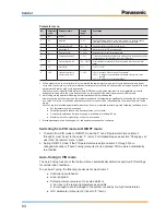
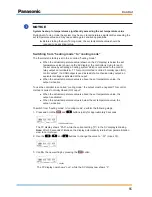
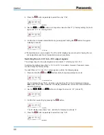
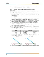
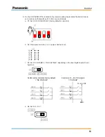
6. On the CZ-CAPBC2 PCB, located on the lower mounting board inside the AHU Kit enclo-
sure, make sure that switches S1 to S4 are set as follows:
a. S1: Set to “OFF-ON-OFF-ON” (factory default on AHU Kit)
b. S2: All jumpers are intact, i e. no jumper has been cut.
c. S3: Set to “VOLTAGE” or “NO VOLTAGE”, depending on the local digital input (DI) con-
figuration.
Control via dry contacts (factory default)
= “NO VOLTAGE”
Control via 12 – 24 V DC signals
= “VOLTAGE”
12 –24 V DC
GND
d. S4: Set to “0–10 V“.


