


54
Electrical Wiring
NOTICE
Overheating of terminals with resulting unit malfunction or even fire due to loose wiring
Loose wiring may cause the terminal to overheat resulting in unit malfunction or a fire hazard.
► When connecting each power wire to the terminal, follow the instructions on
how to connect wiring to the terminal (see next section) and fasten the wire
securely with the terminal screw.
► Check and ensure that all wiring is tightly connected.
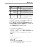
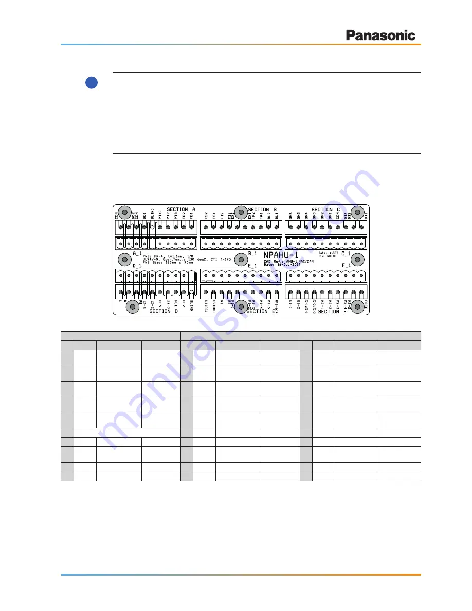
5.4 Terminal block layout
Section A
Section B
Section C
No. Name
Description
Note
No. Name
Description
Note
No. Name
Description
Note
1 FD1
External fan drive
12 V DC
1 BL1
Discharge
temperature
5 V DC
1 DI1
Digital Input 1
max. 24 V DC / 5 mA
2 FD2
External fan drive
12 V DC
2 BL2
Discharge
temperature
5 V DC
2 DI2
Digital Input 2
max. 24 V DC / 5 mA
3 PT8
External temp.
sensor
10 V DC
3 TA1
Suction temperature
5 V DC
3 DI3
Digital Input 3
max. 24 V DC / 5 mA
4 PT9
External temp.
sensor
10 V DC
4 TA2
Suction temperature
5 V DC
4 COM
Digital Inputs COM
max. 24 V DC / 5 mA
5 PT10
External temp.
sensor
10 V DC
5 EX1
EXCT contact
5 V DC
5 ON1
Option connector
COM
12 V DC
6 Blind
6 EX2
EXCT contact
5 V DC
6 ON2
Defrost
12 V DC
7 D01
Operation signal
max 230 V AC / 3 A
7 FI1
Filter contact
5 V DC
7 ON3
Th ON
12 V DC
8 COM
COM operation
signal
max 230 V AC / 3 A
8 FI2
Filter contact
5 V DC
8 ON4
Cool
12 V DC
9 D02
Alarm signal
max 230 V AC / 3 A
9 FS1
Float switch
5 V DC
9 ON5
Heat
12 V DC
10 COM
COM alarm signal
max 230 V AC / 3 A
10 FS2
Float switch
5 V DC
10 ON6
Fan mode
12 V DC
!