67
Control
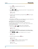
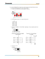
5. Use the
and
buttons to change the value to either “1” for “output 2 ... 10V” or “2”
(= factory setting) for „output 0 ... 10V“.
6. Confirm the complete parametrization by pressing and holding the
button for approxi-
matedly 3 seconds.
1 x for 3 sec.
Parametrization is now complete. The PV and SV displays have returned to showing the cur-
rent temperature and the set temperature values respectively.
7.2.3 Initial Settings
Depending on how the thermostat is used in each individual application, its settings must be
adjusted for the relevant case.
Case 1: Controlling the room supply air temperature
To set the thermostat for controlling the room supply air temperature, perform the following
steps:
1. On the thermostat, switch to PID mode by entering the “Parameter” menu and setting pa-
rameters P, I and D to the values given below (see “7.2.2 Operation – Changing values in the
‘Parameter’ menu”).
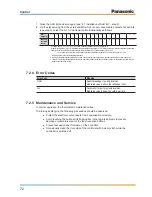
AHU situation
P
I
D
Capacity high in respect to lower air volume flow
7
120
3
Capacity low in respect to higher air volume flow
3
180
10
In case the temperature is not stable during operation, these values may be adjusted manu-
ally at a later stage.
2. On the thermostat, switch to cooling or heating mode, depending on the AHU requirements
(see “7.2.2 Operation – Switching from ‘heating mode’ to ‘cooling mode’”).
3. On the thermostat, change the set temperature value (T
set
) as required (see “7.2.2 Opera-
tion – Changing the set temperature value”).
In this case, the set temperature value represents the desired room supply air temperature.
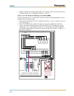
4. Open the AHU Kit enclosure (see “4.1 Installation of AHU Kit“ – step 2), and remove the up-
per mounting board.
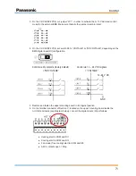
5. On the CR-CAPBC2 PCB, located on the lower mounting board inside the AHU Kit enclo-
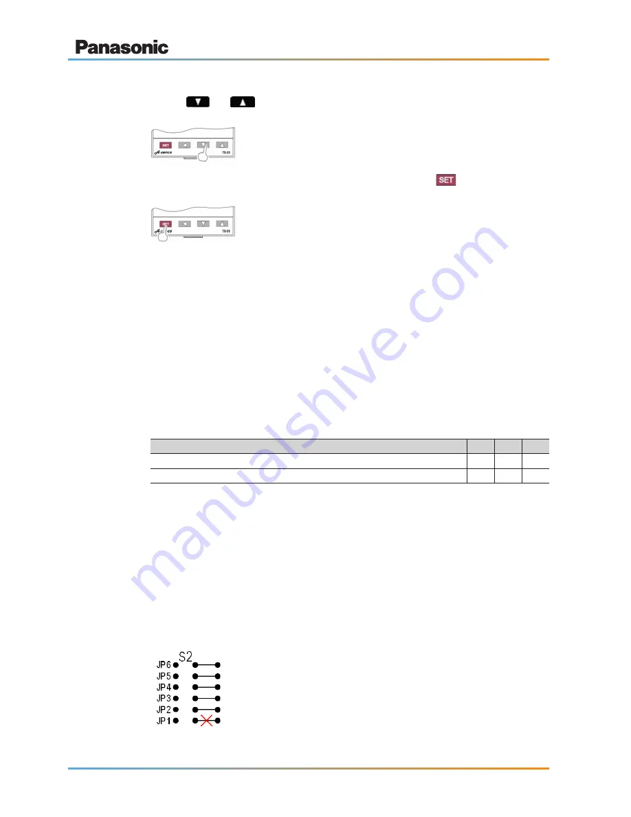
sure, cut jumper “JP1”, in order to activate the 0–10 V control mode for the thermostat. Make
sure that all other jumpers remain intact.


