


6
Introduction
Overview of functions
System configuration
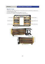
Connect various ports of the unit to a power source and a server according to the functions to be used.
In addition, install DA control software to the server to be connected to the unit. For more information on how to
install, refer to the Install Guide.
≥
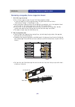
When adding Extension Modules (with the Writer Unit), they need to be added in increments of two. Connect two
SAS cables (straight) and one SAS cable (branch) to each pair of Extension Modules to be added.
Use the specified optional SAS cables.
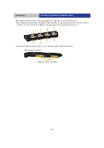
There are two types of drive interface cables (SAS cables), distinguished by the shape of their server-side
connectors.
∫
Required connections
Base Module and Bottom Module/Control Unit/Writer Unit: Uses a control interface port
External power supply: Uses the power connector
Server: Uses a drive interface port and a control interface port
Type SFF-8088 Mini-SAS
Type SFF-8644 Mini-SASHD
`
Straight SAS cable 2.5 m (98.4
q
) (LB-XA25A0G)
`
Straight SAS cable 2.5 m (98.4
q
) (LB-XA25H0G)
`
Branch SAS cable 2.5 m (98.4
q
) (LB-XA25B0G)
`
Branch SAS cable 2.5 m (98.4
q
) (LB-XA25J0G)
`
Straight SAS cable 2.0 m (78.7
q
) (LB-XA20A0G)
`
Straight SAS cable 2.0 m (78.7
q
) (LB-XA20H0G)
`
Branch SAS cable 2.0 m (78.7
q
) (LB-XA20B0G)
`
Branch SAS cable 2.0 m (78.7
q
) (LB-XA20J0G)
The unit
External power
supply
Server
(DA control
software)
Extension Module
(without the Writer
Unit)
Base Module
Extension Module
(with the Writer Unit)
Bottom Module
System configuration example
Exclusive use connection cable A
Exclusive use connection cable B
DC cable (+24 V)
DC cable (+24 V/+12 V)
SAS cable (Straight)
SAS cable (Branch)
Client PC
Client PC
Mail Server
Web interface
/SNMP


![Lambrecht power[cube] 30.95800.015000 Manual preview](http://thumbs.mh-extra.com/thumbs/lambrecht/power-cube-30-95800-015000/power-cube-30-95800-015000_manual_3388101-01.webp)


