


Page 1-69
REGULAR
MAINTENANCE
1
Replacing the Consumable Parts
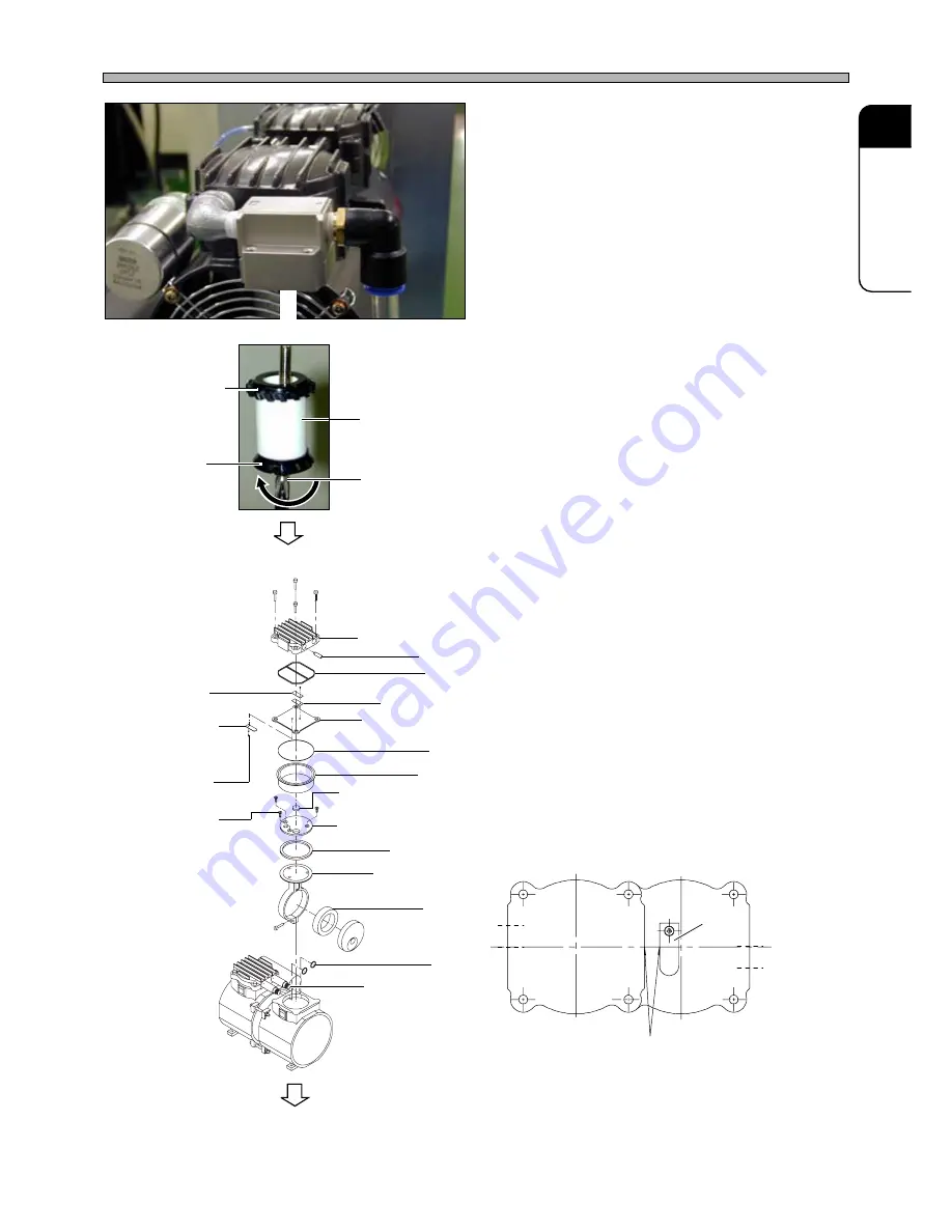
5.
Remove the bolt and exchange the
element.
6.
Exchange the intake valve and the
exhaust valve.
∗
For tightening each valve with the M3 round
head small screw, apply a little bit of
Threadlockers (LOCTITE No. 242) to the point
of the screw. (Tightening torque is 98.07
N•cm)
∗
Check that the intake valve and exhaust valve
is set parallel to the center of the holes (intake
and exhaust opening) and the side of the
plate.
4T3C-E-MMA01-A09-02
4T3C-024P
Filter element
Deflector
4T3C-023P
Phillip driver
To the next page
4T3C-038E
Baffle
M3 round head
small screw
M4 countersunk
head small screw
Check the parallelism.
Exhaust hole
Intake hole
493C-048E
4T3C-034E
Intake
valve
Pump head cover
Silencer
Gasket
Exhaust valve
Exhaust valve
holding plate
Pump head plate
Pump head cover
(Intake valve)
O-ring
Cylinder
Intake valve interference
prevention rubber
Cup packing retainer
Cup packing
Connecting rod
Bearing
O-ring
Connector tubes


