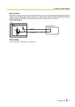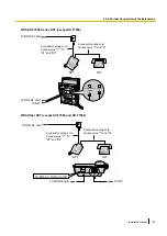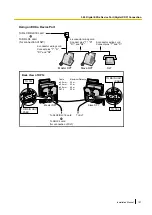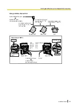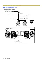
External Sensor
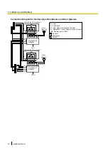
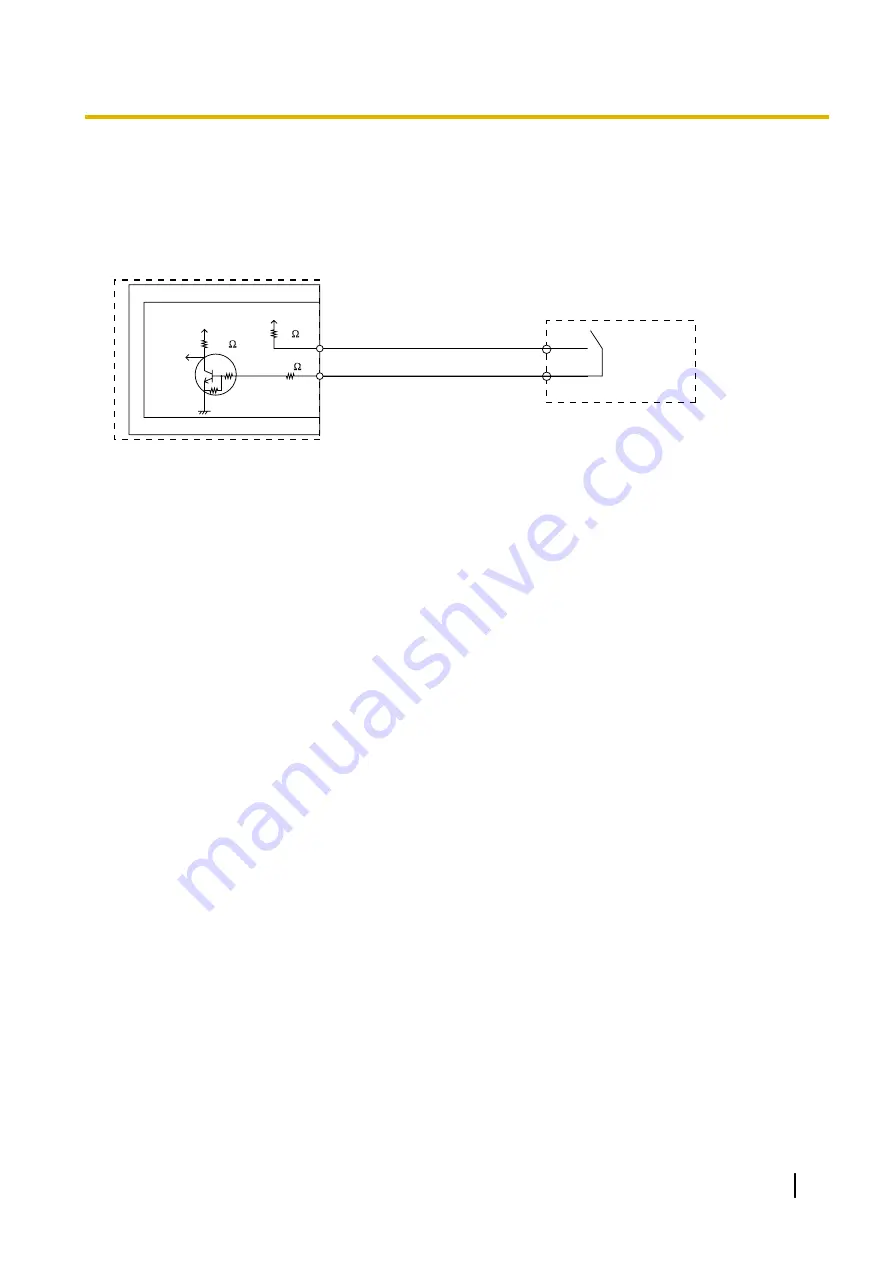
Power to the external sensor is provided from the EIO4 card and must be grounded through the EIO4 card as
indicated in the diagram below. A pair of "sensor" and "common" lines are connected to the EIO4 card for each
external sensor. The PBX detects input from the sensor when the signal is under 100
W
.
Connection Diagram
External Sensor
sensor
common
I/O
EIO4
OPB3
PBX
+5V
+5V
10K
33
33
4.7K
4.7K
External Relay
Current Limit: 24 V DC/30 V AC, 1 A maximum
Installation Manual
97
3.7.4 EIO4 Card (KX-TDA0164)
Summary of Contents for KX-NCP1000
Page 42: ...42 Installation Manual 2 1 3 Activation Key File ...
Page 134: ...134 Installation Manual 4 3 1 Installing and Starting the Maintenance Console ...
Page 146: ...146 Installation Manual 5 1 5 Troubleshooting by Error Log ...
Page 147: ...Section 6 Appendix Installation Manual 147 ...
Page 151: ...Index Installation Manual 151 ...

