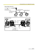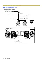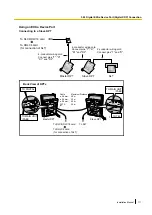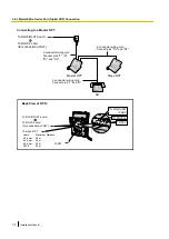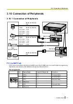
Connection
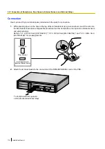
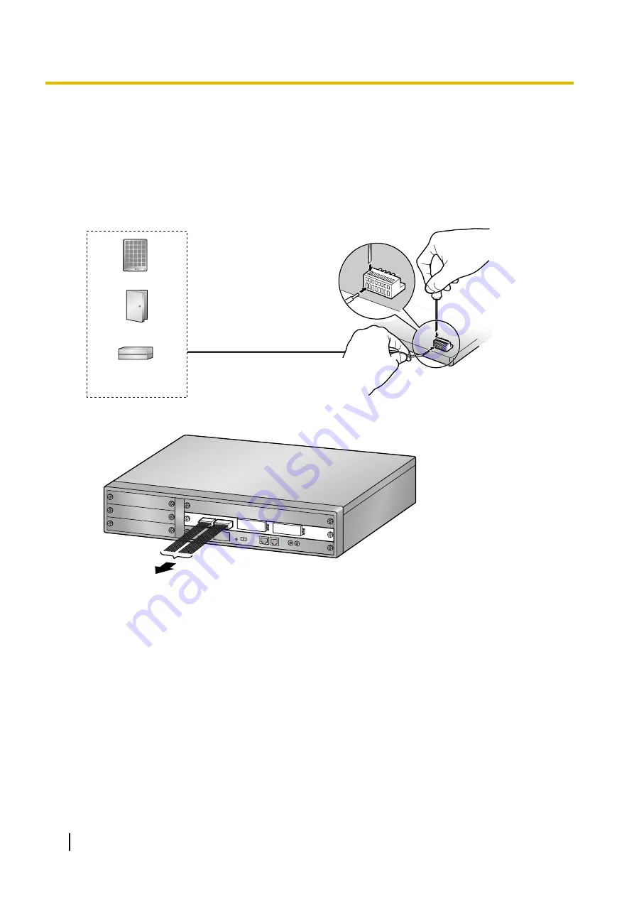
Use 8-pin and 10-pin terminal blocks (included with the card) for connection.
1.
While pressing down on the hole at the top of the terminal block using a screwdriver, insert the wire into
the side hole as shown below. Repeat this procedure for other doorphones, door openers, external sensors,
and external relays.
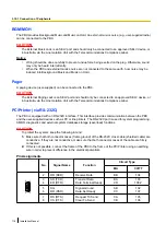
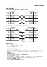
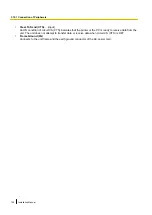
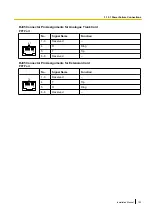
Refer to "3.7.2 DPH4 Card (KX-TDA0161)", "3.7.3 DPH2 Card (KX-TDA0162)", and "3.7.4 EIO4 Card
(KX-TDA0164)" for pin assignments.
Doorphone
Door Opener
External Sensor/
External Relay Device
2.
Attach the terminal blocks to the connectors of the DPH4/DPH2/EIO4 card on the PBX.
To doorphones/door openers/
external sensors/external relays
116
Installation Manual
3.9.1 Connection of Doorphones, Door Openers, External Sensors, and External Relays
Summary of Contents for KX-NCP1000
Page 42: ...42 Installation Manual 2 1 3 Activation Key File ...
Page 134: ...134 Installation Manual 4 3 1 Installing and Starting the Maintenance Console ...
Page 146: ...146 Installation Manual 5 1 5 Troubleshooting by Error Log ...
Page 147: ...Section 6 Appendix Installation Manual 147 ...
Page 151: ...Index Installation Manual 151 ...


