4
1 Safety Precautions
1. Before servicing, unplug the power cord to prevent electrical shock hazard.
2. When replacing parts, use only manufacture’s recommended components for safety.
3. Check the condition of power cord. Replace if wear or damage is evident.
4. After servicing, be sure to restore the wire dressing, insulation barriers, insulation papers, shields, etc.
1.1.
Standard for Repair Service
Repair service shall be provided in accordance with repair technology information such as service manual
so as to prevent fires, injury or electric shock, which can be caused by improper repair work.
1. When performing repairs, neither the products nor its parts or components shall be modified.
2. If cable assembly is supplied as the smallest unit when servicing, make sure to replace
the cable assembly.
1.2.
For Service Technicians
ICs and LSIs are vulnerable to static electricity.
When repairing, the following precautions will help to prevent recurring malfunctions.
1. Cover the plastic parts with aluminum foil.
2. Ground the soldering irons.
3. Use a conductive mat on the worktable.
4. Do not grasp IC or LSI pins with bare fingers.
1.3.
About Lead Free Solder (PbF: Pb free)
Note
•
In the information below, Pb, the symbol for lead in the periodic table of elements, will refer to standard solder or solder that con-
tains lead.
•
We will use PbF when discussing the lead free solder used in our manufacturing process which is made from Tin (Sn), Silver
(Ag), and Copper (Cu).
•
This model, and others like it, manufactured using lead free solder will have PbF stamped on the PCB. For service and repair
work we suggest using the same type of solder.
Distinction of PbF PCB
•
PCBs (manufactured) using lead free solder will have a PbF stamp on the PCB.
Caution
•
PbF solder has a melting point that is 50
- 70
F, (30
- 40
C) higher than Pb solder.
Please use a soldering iron with temperature control and adjust it to 700
±
20
F (370
±
10
C).
• Exercise care while using higher temperature soldering irons.: Do not heat the PCB for too long time in order to
prevent solder splash or damage to the PCB.
•
PbF solder will tend to splash if it is heated much higher than its melting point, approximately 1100
F (600
C).
•
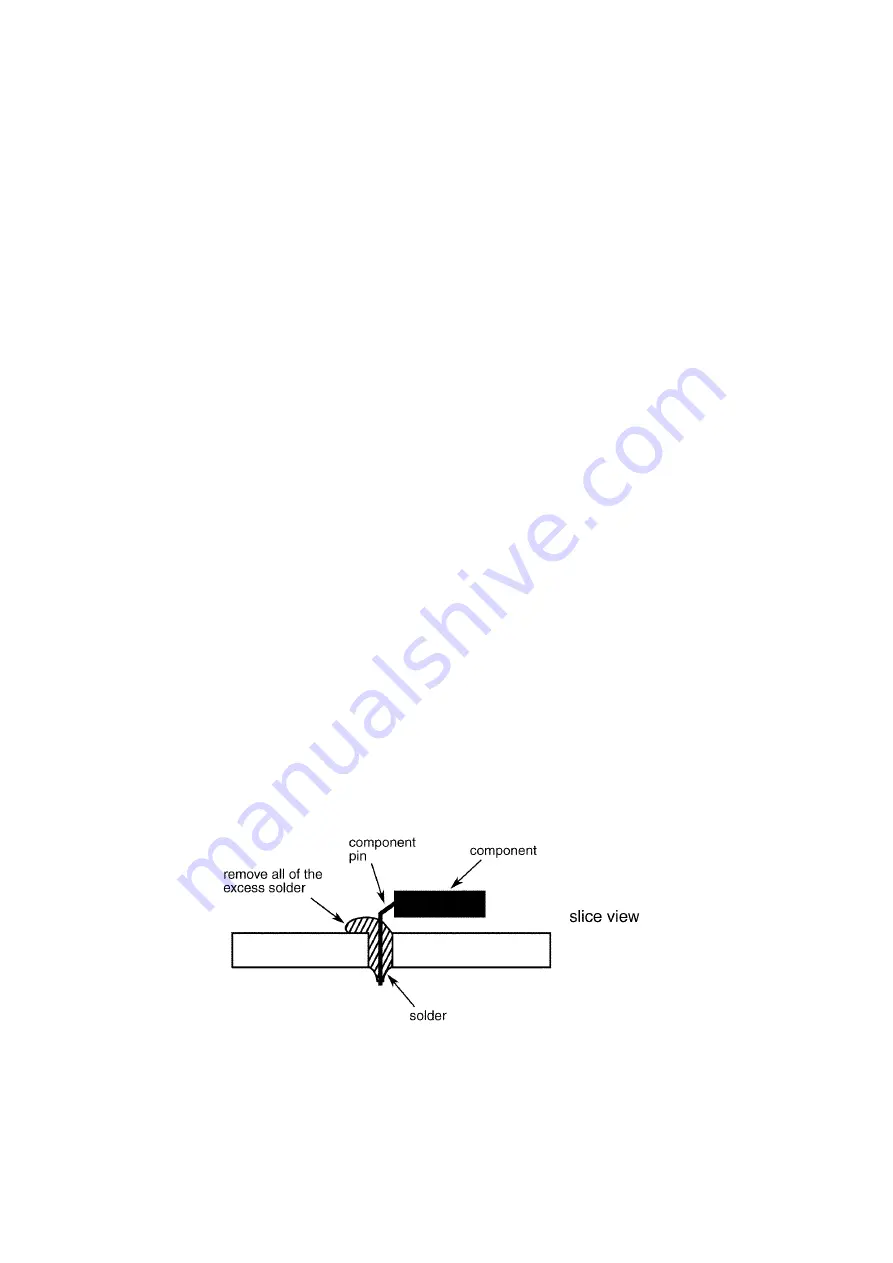
When applying PbF solder to double layered boards, please check the component side for excess solder which may flow onto
the opposite side (See figure below)
Summary of Contents for KV-S1057C
Page 7: ...7...
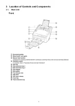
Page 9: ...9 3 Location of Controls and Components 3 1 Main Unit...
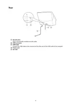
Page 10: ...10...
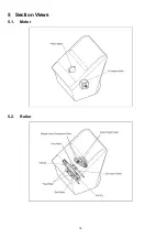
Page 16: ...16 5 Section Views 5 1 Motor 5 2 Roller...
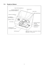
Page 17: ...17 5 3 Board and Sensor...
Page 31: ...31 7 3 8 Wiring of Upper Chassis...
Page 128: ...128 14 Exploded View and Replacement Parts List...
Page 133: ...133 14 3 Feed Tray Assembly 302 305 302 303 307 301 306 305 302 304 Feed Tray Assembly...
Page 188: ...Index 74 8 Operating Manual Table of Contents...
Page 255: ...PNQX6995ZA DD0914HS0 Panasonic System Networks Co Ltd 2014...

