b.
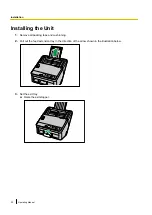
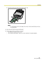
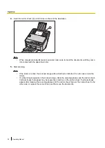
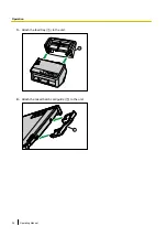
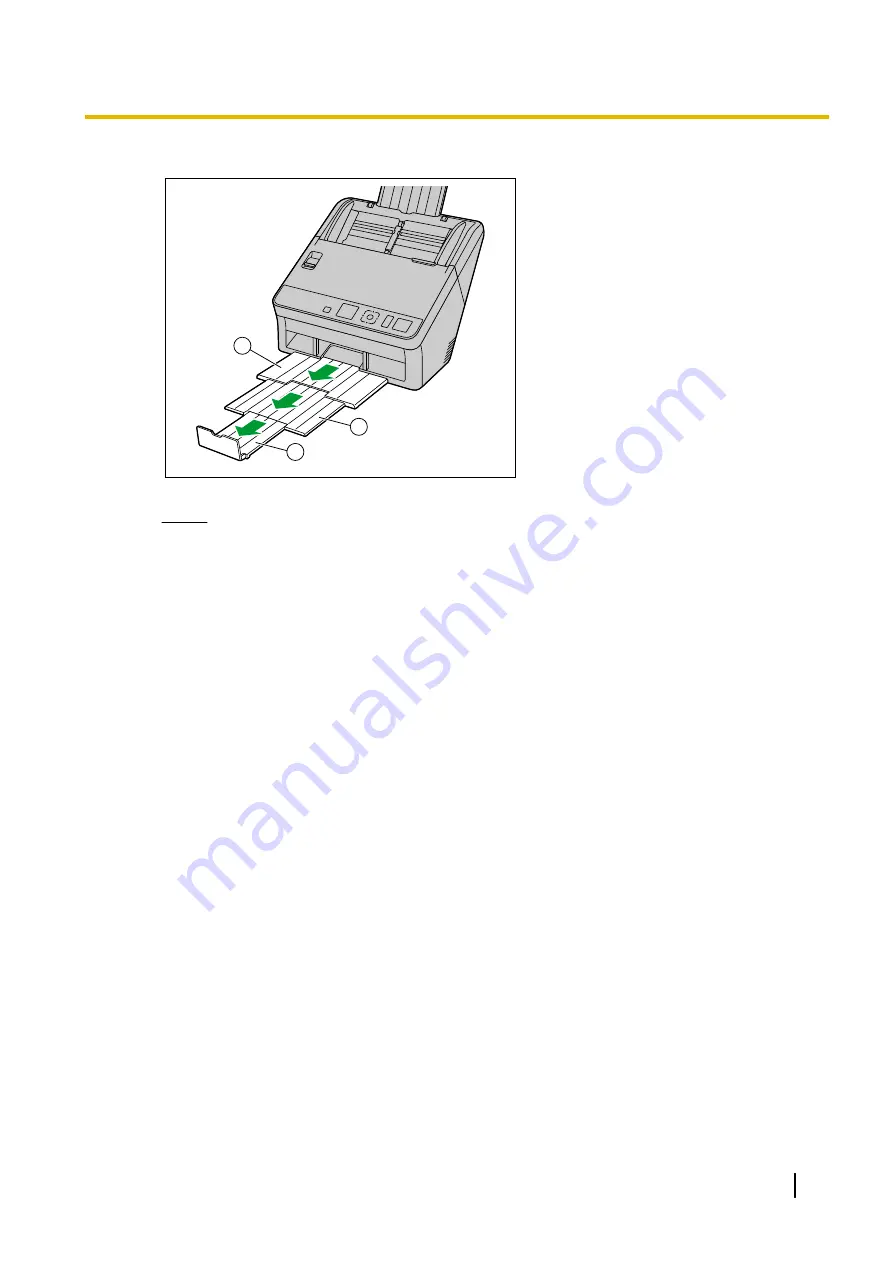
Pull out the exit tray (
A
) and the exit extension trays (
B
,
C
).
2
1
3
Notice
•
Do not forcefully pull out the exit stopper, the exit tray, or the exit extension trays. Doing so
may damage them.
4.
Plug in the power cord and connect the USB cable.
5.
Press the power button to turn ON the unit’s power.
•
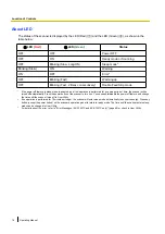
The LED (Green) will flash and then turn on.
•
If the hardware wizard appears, follow the on-screen instructions to complete installation.
Operating Manual
21
Installation
Summary of Contents for KV-S1057C
Page 7: ...7...
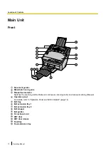
Page 9: ...9 3 Location of Controls and Components 3 1 Main Unit...
Page 10: ...10...
Page 16: ...16 5 Section Views 5 1 Motor 5 2 Roller...
Page 17: ...17 5 3 Board and Sensor...
Page 31: ...31 7 3 8 Wiring of Upper Chassis...
Page 128: ...128 14 Exploded View and Replacement Parts List...
Page 133: ...133 14 3 Feed Tray Assembly 302 305 302 303 307 301 306 305 302 304 Feed Tray Assembly...
Page 188: ...Index 74 8 Operating Manual Table of Contents...
Page 255: ...PNQX6995ZA DD0914HS0 Panasonic System Networks Co Ltd 2014...


