


6
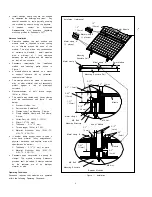
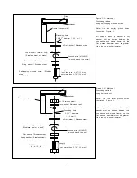
Ground Location
(smaller holes for self-tapping machine screw)
Junction Box
Label
Backside
The ground holes
are on the backside of the
module frame.
Figure 3.1
Module Ground Position
Ground Location
(larger holes for bolt and nut)
Acceptable grounding wire is following.
Ilsco Corp. GBL-4DBT 10-14AWG-Solid,
4-6,
8,
10-14AWG-Strand
Burndy L L C CL501TN 14AWG-Solid, 14-
4AWG-Strand
Tyco
Electronics
Corp.
1954381-
1/1954381-2 10-12AWG Solid
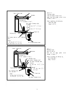
Each ledge on the module frame has two
smaller holes for self-tapping machine
screws (0.165’‘diameter (4.2 mm)) and
two larger holes for bolts (0.205’‘diameter
(5.2 mm)). These ground holes are
marked with a “G” adjacent to their
location on the frame rail (see Figure 3.1).
Ground wires must be connected to the
module’s metal frame at one of these
locations.
Lay-in lugs or grounding clips can be used
to ground Panasonic PV modules. Both
methods are explained below, please
choose one.
Grounding Locations (or grounding holes)
Using a self-tapping machine screw
(see
Figures 3.2 and 3.4)
If using this method, use one of the
smaller holes with diameter of 0.165’‘ (4.2
mm)
The self-tapping machine screw size must
be No.10 (0.190’‘diameter (4.83mm)).
This method requires a minimum number of
threads-per-inch to achieve an adequate
electrical connection. For a single screw,
the thread pitch must be at least 32
threads per inch (TPI). A single screw
less than 32 TPI does not provide
sufficient thread contact. Note: Self-tapping
machine screws are also called thread
cutting screws.
Recommended torque value in tightening
self-tapping machine screw is 2.3 N.m
(20in-lb).
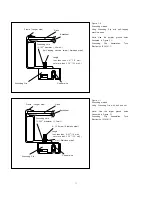
Using bolt and nut
(see Figures 3.3 and 3.5)
If using this method, use one of the larger
holes with diameter of 0.205’‘ (5.2 mm)
The bolt and nut size should be No.8
(0.164’‘diameter (4.16 mm)), or
No.10 (0.190’‘diameter (4.83 mm))
or M5 (0.197’‘diameter (5.0 mm)).
Star washers must be used to make
contact through the anodization of the
module frame.
In this case, the screw threads are not
providing the electrical ground contact.
Recommended torque value in tightening
bolt and nut is 2.3 N.m (20in-lb).
Grounding Methods
Where common grounding hardware (nuts,
bolts, star washers, spilt-ring lock washers,
flat washers and the like) is used to
attach a listed grounding/bonding device,
the attachment must be made in
conformance with the grounding device
manufacturer's instructions.
Common hardware items such as nuts,
bolts, star washers, lock washers and the
like have not been evaluated for electrical
conductivity or for use as grounding devices
and should be used only for maintaining
mechanical connections and holding electrical
grounding devices in the proper position for
electrical conductivity. Such devices, where
supplied with the module and evaluated
through the requirements in UL 1703, may
be used for grounding connections in
accordance with the instructions provided
with the module.
Wire connection using cup washers
(see Figures
3.2 and 3.3)
The use of cup washers is to prevent wire
from slipping out from under the screw
head (and/or the flat washer).
Make sure that the cup washer is placed
between the wire and the module frame.
Choose an adequate size for the cup
washer and the flat washer so that the
wire is fully clamped between them.
Note: Cup washers are also called terminal
cup washers.
The cup washers should be stainless steel,
or a cup washer made of brass may be
used only if a large flat washer made of
stainless steel is inserted between the
module frame and the cup washer.
Choose the adequate size for the large flat
washer (between the module frame and
the cup washer) so that the cup washer
doesn’t contact the module frame and is
fixed stably to the module frame.
Method 1- Use a self-tapping machine screw
(see Figures 3.1 and 3.2)
If using this method, use one of the
smaller holes with diameter of 0.165’‘ (4.2
mm)
The self-tapping machine screw size must
be No.10 (0.190’‘ diameter (4.83mm)).
This method requires a minimum number of
threads-per-inch to achieve an adequate
electrical connection. For a single screw,
the thread pitch must be at least 32
threads per inch (TPI). A single screw
less than 32 TPI does not provide
sufficient thread contact. Note: Self-tapping
machine screws are also called thread
cutting screws.
Method 2- Use a bolt and nut (see Figures 3.1
and 3.3)
If using this method, use one of the larger
holes with diameter of 0.205’‘ (5.2 mm)
The bolt and nut size should be No.8
(0.164’‘ diameter (4.16 mm)), or No.10
(0.190’‘ diameter (4.83 mm)) or M5


