


5
1)
Terrestrial applications only—no outer space
or Special Conditions (see below).
2)
The ambient temperature must be within –
20°C (-4°F) to 40°C (104 °F). The
temperature limits are defined as the
Monthly Average High or Low of the
installation site.
3)
The wind pressure load of the installation
site should be less than 2,400N/m
2
(50PSF)
4)
Some environmental conditions could apply.
Please refer to Panasonic’s warranty
exclusions.
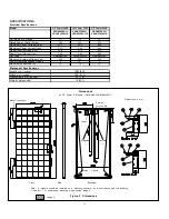
SPECIFICATIONS
Notes on Specifications
1)
Rated electrical characteristics are within –
5% to +10% of the values measured at
Standard Test Conditions (STC). STC
conditions are; Irradiance of 1000W/m
2
,
25°C cell temperature, and solar spectral
irradiance per IEC 60904-3. Note: At the
time of shipment, Panasonic guarantees the
output level of its modules to be -0/+10%
against Rated Power in SPECIFICATIONS
based on factory inspection at STC
conditions.
2)
Under real conditions, a photovoltaic module
may experience conditions that produce
more current and/or voltage than
reported at Standard Test Conditions.
Therefore, the Isc value of modules should
be multiplied by a factor of 1.25 to
determine ampacity. An additional factor of
1.25 may be required for sizing conductors,
fuses, disconnects, etc. Please refer to
section 690.8 of the National Electric Code
(NEC) for guidelines. The Voc must be
factored according to the lowest recorded
ambient temperature recorded for the
location where the modules will be installed.
Please refer to section 690.7 of the NEC
for more information regarding voltage
temperature factors.
3)
The current output for the modules shown
in the SPECIFICATIONS section is
measured at Standard Test Conditions.
These conditions may not be frequently
observed in actual practice.
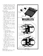
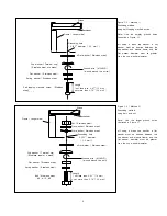
Mechanical Loading
The modules should be mounted at the
four (4) quarter points by the means
shown in Figure 2.
This method offers a maximum load of
2,400N/m2 (50PSF) in a static state on
the module surface.
Note: This mechanical loading value was
tested using the mounting device specified
in section “Notes on Installation”.
WIRING
General
All wiring should be done in accordance
with applicable electrical codes.
Wiring methods should be in accordance
with the NEC in USA or CEC in Canada.
A qualified, licensed professional should do
all wiring.
Wiring should be protected to help ensure
personal safety and to prevent damage.
All modules connected in series should be
of the same model number and/or type.
Do not connect modules in parallel without
using a connection box that connects
appropriate FUSE for each series string or
each module.
Do not disconnect terminals while modules
generate electricity and connect electrical
load to avoid the hazard of electrical shock.
To avoid the hazard of electric shock and
sparks, please connect each cable after
confirming the polarity of them is correct.
Cable conduits should be used in locations
where the wiring is inaccessible to children
or small animals.
Module Wiring
The number of modules that can be wired
in series is recommended to be ten (10)
or fewer. If connecting eleven (11)
modules in series, check local temperature
conditions and follow the National Electric
Code (690.7) to ensure compliance with
maximum voltage limitations.
Modules are not designed for “off-grid” or
battery charging systems, because of their
operating voltage. Therefore, it is not
recommended to use them for charging
batteries.
These modules contain factory installed
bypass diodes. If these modules are
incorrectly connected to each other, the
bypass diodes, cable, or junction box may
be damaged.
Array Wiring
The term “array” is used to describe the
assembly of several modules on a support
structure with associated wiring.
Use copper wire which insulation is sunlight
resistant and can withstand the maximum
possible system open circuit voltage.
Interconnection of modules must be
performed in a professional fashion. Wires
should be secured and only reasonable
slack should be allowed.
Check local codes for requirements.
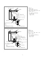
Earth Ground Wiring
A module with exposed conductive parts is
considered to be in compliance with UL
1703 only when it is electrically grounded
in accordance with the instructions presented
below and the requirements of the National
Electrical Code.
All modules should be grounded. All
structures or metallic components in direct
contact with the modules or electric wires
should be properly grounded too. To avoid
the hazards of electric shock or fire,
modules should be grounded by the frame
only at the locations marked in this manual
(see grounding methods below).
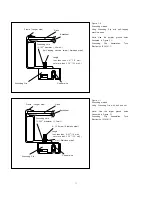
The array frame shall be grounded in
accordance with NEC Article 250 (USA)
or the CEC in Canada.
Bonding shall be by a positive means,
such as clamping, riveting, bolted or
screwed connectors, or welding, soldering or
brazing. If the bonding means depends
upon screw threads two or more screws or
two full threads of a single screw must
engage the metal
Great care should be exercised to ensure
that corrosion caused by the grounding
means be avoided.
Corrosion can increase the resistance of the
grounding connection on the module, or can
even cause the grounding connection to fail
entirely. Corrosion can be caused by the
effects of weather, humidity, dirt and so on.
It can also be caused when two dissimilar
metals are in contact (galvanic reaction).
The
module
frame
material
is
aluminum/magnesium alloy.
All fasteners (nuts, bolts, washers,
screws, etc.) must be stainless steel
unless otherwise specified.
Length of self-tapping machine screw or
bolt should not be more than 0.78’’ (20
mm) in order to avoid contacting the
back-sheet of the module.


