background image


Install modules where they are not shaded 
by obstacles like buildings and trees.  Pay 
special  attention  to  avoid  partially  shading 
the modules by objects during the daytime.  


If  needed,  contact  an  Authorized 
Representative  with  questions  regarding 
mounting profiles for Panasonic HIT

®


Notes on Installation  


Clearance  between  the  roof  surface  and 
module  frame  is  required  to  allow  cooling 
air  to  circulate  around  the  back  of  the 
module.  This  also  allows  any  condensation 
or  moisture  to  dissipate.    Install  modules 
with  a  minimum  of  1  inch  clearance 
between  the  roof  surface  and  the  modules 
so that air can circulate. 


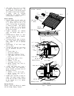
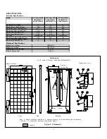
Panasonic  recommends  the  installation 
method  and  mounting  profile  shown  in 
Figure 1  


A module should be attached on a mount 
or  support  structure  rail  by  corrosive-
resistant metal clamps. 


The  clamps  should  be  made  of  aluminum 
alloy  or  other  material  that  will  reasonably 
protect  against  a  risk  of  electrolytic 
corrosion.   


Recommendation  of  bolt  torque  range: 
16N.m to 20N.m  


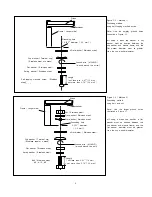
The module was tested using Unirac clamps 
with  the  specifications  see  figure  1  and 
below;  


Provider: UniRac, Inc. 


Part number: SolarMount

®


Clamps type: Top Mounting  Clamps 


Clamp  size:Mid  clamp  and  End  clamp, 
C size, 


Unirac Part No. 302003, 302101  


Width: 1.5”(38 mm) 


Thickness :  0.12”(3 mm) 


Torque range: 16N.m to 20N. 


Material:  Aluminum  Alloy  (6005-T5, 
6105-T5, 6061-T6) 


If  another  clamp  except  Unirac  is  used  it 
must  have  material  (alloy  designations), 
physical  dimension  and  capture  area  with 
specifications as bellow; 


Thickness :  0.12”(3 mm) or more 


Material:  Aluminum  Alloy  (6005-T5, 
6105-T5, 6061-T6) 


Panasonic does not provide a warranty  for 
clamps.  The  module  warranty  Panasonic 
provides shall be voided if clamps selected 
by  the  customer  are  of  an  improper 
material or size 


Operating Conditions 

Panasonic  requires  that  modules  are  operated 
within the following Operating Conditions: 


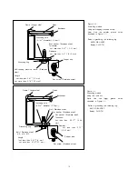
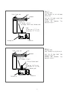
Installation (reference) 

Solar Module 

Metal clamp B 
(2 places) 

Metal clamp A 
(2 places) 

Mounting 
Structure Rail 

Metal clamp B 

Solar Module 

Metal clamp A 

Mounting Structure Rail 

Metal clamp B 

Module 

Mounting Structure 

M8 Nut 

Metal clamp A 

M8 Bolt 

M8 Bolt 

M8 Nut 

End of Module 

Between Modules 

Figure 1.  Installation 

1.5” 
(38mm) 

0.12”  
(3mm) 

0.2” (5mm) 

1.37” 
(35mm) 

0.18” 
(4.6mm) 

Mounting Structure 

Module 

0.62” 
(16mm) 

0.43” 
(11mm) 

0.2” (5mm) 

0.12”  
(3mm) 

0.2”  
(5mm) 

0.2”  
(5mm) 

0.2”  
(5mm) 

1.5” 
(38mm) 

Summary of Contents for HIT Power 240S Series

Page 1: ...is part of the Panasonic Group and is in charge of the manufacturing process for Panasonic HIT Model No HIT Power 240S VBHN240SA11 and 11B HIT Power 235S VBHN235SA11 and 11B HIT Power 230S VBHN230SA1...

Page 2: ...sed Content New Edition 2013 4 19 2nd Edition 2015 3 18 1 System Fire Class Rating 2 Trademark 3 Front cover Grounding 1 Addition of System Fire Class Rating 2 Explanation of trademark 3 According to...

Page 3: ...ss diodes Do not touch a module unnecessarily The glass surface and frames get hot There is a risk of burn CAUTIONS Use a module for its intended purpose only Do not treat the back sheet frame or fron...

Page 4: ...ons see figure 1 and below Provider UniRac Inc Part number SolarMount Clamps type Top Mounting Clamps Clamp size Mid clamp and End clamp C size Unirac Part No 302003 302101 Width 1 5 38 mm Thickness 0...

Page 5: ...ock To avoid the hazard of electric shock and sparks please connect each cable after confirming the polarity of them is correct Cable conduits should be used in locations where the wiring is inaccessi...

Page 6: ...olts star washers spilt ring lock washers flat washers and the like is used to attach a listed grounding bonding device the attachment must be made in conformance with the grounding device manufacture...

Page 7: ...his will terminate the wire For more information please refer to Instruction sheet issued by Tyco Electronics Using a Grounding Clip with bolt and nut Use Tyco Electronics 1954381 2 as grounding clip...

Page 8: ...ation use or maintenance by using this manual Panasonic assumes no responsibility for any infringement of patents or other rights of third parties which may result from use of modules No license is gr...

Page 9: ...frame and the flat washer diameter must be greater than the cup washer diameter If using a brass cup washer a flat washer must be inserted between the cup washer and module frame and the flat washer...

Page 10: ...eter 5 2mm Flat washer Stainless steel Thickness not less than 0 037 0 94 mm Diameter not less than 0 75 19 05 mm Grounding Lug Bolt Stainless steel 8 10 M5 Nut Stainless steel Copper wire Set screw S...

Page 11: ...und holes illustrated in Figure 3 1 Grounding Clip Assemblies Tyco Electronics 1954381 2 Glass Backsheet Frame Longer side Grounding hole 0 205 diameter 5 2mm Grounding Clip 8 32 Screw Stainless steel...

Page 12: ...System Voltage Voc 600 600 600 Factory Installed Bypass Diodes 3 3 3 Maximum series fuse A 15 15 15 Mechanical Specifications Length mm inches Width mm inches Frame Depth mm inches Weight kg pounds 35...

Reviews: