


7
(0.197’‘ diameter (5.0 mm)).
Star washers must be used to make
contact through the anodization of the
module for this method.
In this case, the screw threads are not
providing the electrical ground contact.
Using lay-in lug with self tapping machine screw
If using this method, please follow
instructions in previous section regarding
using self-tapping machine screws.
Use a grounding tin plated solid copper
lay-in lug rated for direct burial and
outdoor use. Lug must be used ILSCO
GBL-4DBT, Burndy CL501TN.
The self-tapping machine screw size must
be No.10 (0.190’‘ diameter (4.83mm)).
This method requires a minimum number of
threads-per-inch to achieve an adequate
electrical connection. For self-tapping
machine screws, the thread pitch must be
at least 32 threads per inch (TPI). A
single screw less than 32 TPI does not
provide sufficient thread contact. Note: Self-
tapping machine screws are also called
thread cutting screws.
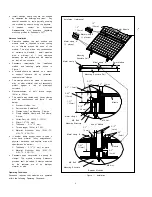
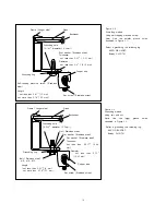
As shown in figure 3.4, attach grounding
lug to module frame using a stainless steel
self-tapping machine screw.
Insert a stainless steel star washer between
the module frame and the lug to penetrate
frame anodization.
Tighten stainless steel set screw at the
torque specified by lug manufacturer to
secure copper wire.
The specified torque is following
Ilsco
Corp.
GBL-4DBT
10-14AWG-Solid -> 20 in-lbs,
4-6AWG-Strand -> 35 in-lbs,
8AWG-Strand -> 25 in-lbs, 10-
14AWG-Strand -> 20 in-lbs
Burndy L L C CL501TN 14AWG-
Solid
->
35
in-lbs,
14AWG-Strand -> 35 in-lbs,
4AWG-Strand -> 45 in-lbs
Recommended torque value in tightening
self-tapping machine screw is 2.3 N.m
(20in-lb).
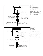
Using a lay-in lug with bolt and nut
If using this method, please follow
instructions in previous section regarding
using bolts and nuts with larger grounding
holes.
Use a grounding tin plated solid copper
lay-in lug rated for direct burial and
outdoor use. Lug must be used ILSCO
GBL-4DBT, Burndy CL501TN.
Attach grounding lug to module frame using
a stainless steel bolt and lock-nut as
shown in figure 3.5.
Tighten stainless steel set screw at the
torque specified by lug manufacturer to
secure copper wire.
Recommended torque value in tightening
bolt and nut is 2.3 N.m (20in-lb).
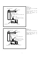
Using a Grounding Clip with self- tapping
machine screw
Use Tyco Electronics 1954381-1 as
grounding clip.
As shown in figure 3.6, place the
grounding clip onto the module frame.
Thread the screw into the hole until the
head is flush with the base and base is
flush with the frame, then tighten the screw
with
1/4
to
1/2
turn.
Recommended torque value in tightening
self-tapping machine screw is between 2.3
and 2.8 Nm.
Insert the wire into the wire slot. Press
down on both ends of the wire.
Manually, or using channel lock pliers, push
the slider over the base until it covers the
base. This will terminate the wire.
For more information, please refer to
Instruction sheet issued by Tyco Electronics.
Using a Grounding Clip with bolt and nut
Use Tyco Electronics 1954381-2 as
grounding clip.
As shown in figure 3.7, place the
grounding clip onto the module frame.
Thread the hex nut onto the end of the
screw, then using a 3/8-in. wrench,
tighten
the
nut.
Recommended torque value in tightening
bolt and nut is between 1.7 and 2.2 Nm.
Insert the wire into the wire slot. Press
down on both ends of the wire.
Manually, or using channel lock pliers, push
the slider over the base until it covers the
base. This will terminate the wire.
For more information, please refer to
Instruction sheet issued by Tyco Electronics.
Module Terminations
A junction box as a terminal enclosure is
equipped for electrical connections.
VBHNxxxSA11 and VBHNxxxSA11B Modules are
equipped with MC
TM
plugs as a terminal
enclosure. Use these MC
TM
plugs for electrical
connections
(see Figure 4.1).
Junction Box and Terminals
Modules are equipped with one junction box
containing terminals for both, positive and
negative polarity, and bypass diodes.
Each terminal is dedicated to one polarity
with the polarity symbols engraved onto the
body of the junction box (see Figure 4.2).
Each terminal is provided with factory
installed lead cables and a latching
connector for series and string connections.
Always use these connectors and do not
detach them from cables.
Latching connectors are type IV and made
by Multi-Contact. Supplied connectors listed
by UL.
In order to comply with NEC 2008, a
locking sleeve needs to be used with all
connectors that are exposed.
The locking sleeve (PV-SSH4) is made
by Multi-Contact and can only be released
with a special tool also made by
Multicontact (PV-MS). Locking sleeves are
not supplied with modules and must be
purchased separately.
Conduit
In applications where wire raceways or
conduit are used, follow the applicable
codes for outdoor installations..
Verify that all fittings are properly installed
to protect wires against damage and
prevent moisture intrusion.
DIODES
Bypass Diodes
When modules in series strings are partially
shaded, it may cause reverse voltage
across cells or modules, because the
current from other cells in the same series
is forced to flow through the shaded area.
This may cause undesirable heating to
occur.
The use of a diode to bypass the shaded
area can minimize both heating and array
current reduction.
Modules are equipped with factory installed
bypass diodes. The factory-installed diodes
provide proper circuit protection for the
systems within the specified system voltage,
so that you do not need any other
additional bypass diodes.
Contact
your
Panasonic
Authorized
Representative for proper diode type, if it is
necessary to add or change diodes due to
system specifications.
MAINTENANCE
Some maintenance is recommended to
maintain optimal output performance of the
solar modules.


