


3
Safety Precautions
General Information
The installation of solar modules requires a
great degree of skill and should only be
performed by qualified licensed professionals,
including, without limitation, licensed contractors
and electricians.
WARNING
All instructions should be read and
understood before attempting to install, wire,
operate, and maintain a photovoltaic module.
Contact with electrically active parts of the
module such as terminals can result in
burns, sparks, and lethal shock whether the
module is connected or disconnected.
The installer assumes the risk of all injury
that might occur during installation, including,
without limitation, the risk of electric shock.
The modules generate DC (direct current)
electrical energy when exposed to sunlight
or other light sources. Even a single
module produces enough voltage and
current, to cause shocks and burns if
safety precautions are not followed.
The shock hazard increases as modules are
connected in parallel, producing higher
current, and as modules are connected in
series, producing higher voltages.
To avoid the hazard of electric sparks,
shock, fire, burns, damage and injury:
Work only in dry conditions, with dry
modules and dry tools.
Do not stand or step on modules. Do not
puncture, cut, scratch or damage the
backsheet of a module. Backsheet damage
will void a module’s Limited Warranty and
may cause fire. Never use modules with a
damaged back sheet.
Do not allow children and unauthorized
persons near the installation or storage site
of modules.
Completely ground all modules.
Do not disassemble a module, attempt any
repair, open the junction box cover, nor
remove any parts installed by Panasonic.
There are no user serviceable parts within
the module or junction box.
Unauthorized persons - except the qualified
licensed professional - should not perform
any electrical work, including wiring,
Wear suitable clothing, guards, eye
protection and gloves to prevent you from
direct contact with 30 VDC or greater.
Wear non-slip gloves and carry modules by
the frame using both hands. Do not
attempt to carry a module by yourself.
Do not carry a module by its wires or
junction box.
Do not drop anything on the surface of a
module.
Ensure all system components are
compatible, and they do not subject the
module to mechanical or electrical hazards.
Sparks may occur; do not install modules
where flammable gases or vapors are
present.
Never rest or leave a module unsupported
or unsecured.
Do not drop modules.
Do not use or install broken modules.
Do not artificially concentrate sunlight on a
module.
Do not touch the junction box terminals.
Do not change the wiring of bypass diodes.
Do not touch a module unnecessarily. The
glass surface and frames get hot. There is
a risk of burn.
CAUTIONS
Use a module for its intended purpose only.
Do not treat the back sheet, frame, or
front surface with paint or adhesives, to
avoid reducing its’ functionality, damage,
and causing inoperable conditions, and
other unknown troubles.
Do not insert PV cable between back side
and mounting structure rail.
GENERAL SAFETY
Follow all permissions, installation and
inspection requirements.
Before installing modules, contact the
appropriate authorities having jurisdiction to
determine permissions, installation and
inspection requirements, which should be
followed.
Electrically ground modules for all systems
of any voltage. If not otherwise specified, it
is recommended that requirements of the
latest National Electrical Code (USA) or
Canadian Electric Code (Canada) or other
national or international electrical standards
be followed. Refer to “Earth Ground
Wiring” section for more information.
Be sure that the building or structure (roof,
façade, etc.) where the modules are being
installed has enough strength to support the
load of the modules.
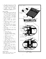
For modules mounted on roofs, special
structures may be required to help provide
proper installation support.
The fire rating of this module is valid only
when mounted in the manner specified in
the mechanical mounting instructions.
Both, roof construction and module
installation design have an effect on the
fire resistance of a building. Improper
installation may contribute to fire hazards.
The models in this instructions are suitable
to maintain the System Fire Class Rating A
when used with a Listed mounting system
and a roof covering that have been rated
as a Class A System when installed on a
steep slope roof and/or a low slope roof
with "Type 2" modules.
Additional devices such as ground fault,
fuses, and disconnects may be required.
Do not use modules of different
specifications in the same system.
Follow all safety precautions of other
system components which are used.
UL Listing Information
To satisfy UL requirements, when installing the
modules, be sure to:
1)
Use only stranded or solid copper single–
conductor sunlight-resistant cable rated for
outdoor use (e.g. type UF or USE) , for
all wiring that is exposed to weather.
2)
Observe the requirements described in
sections labeled INSTALLATION and
SPECIFICATIONS.
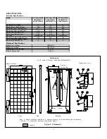
INSTALLATION
General
Please read this guide completely before
installing or using your Panasonic PV modules.
This section contains important electrical and
mechanical specifications.
Modules should be firmly fixed in place in
a manner suitable to withstand all expected
loads, including wind and snow loads.
Metals used in locations that are exposed
to moisture shall not be employed alone or
in combinations that could result in
deterioration or corrosion.


