ー 26 ー
ー 27 ー
■
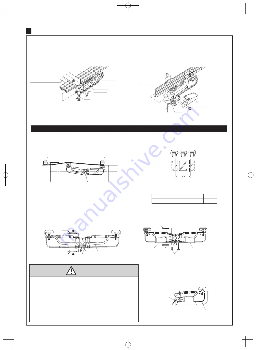
Standard installation
Set the distance between the High-Tro-Reel conductor sliding
surface and collector arm mount rod to 90mm (Central value of the
collector arm permitted movable range 90±20mm).
(Set the distance to 90mm at the hanger bracket section.)
(shown<A>)
When collector arm mount rod set up a referenceposition, the operating
range from 70mm
〜
110mm of collector arm set up to be twisting.
Adjust the arm mount rod between the High-Tro-Reel unit to become 110mm
or less and 70mm or more at the center between hangers, and 70mm or more
at the bracket.
■
Horizontal installation with its opening facing
As shown in a figure,mounted collector arm support parts for transverse on base of
the collector arm.Tightening torque of fixing screws
:
0.98 N
・
m
〜
1.32 N
・
m
Set the distance between the High-Tro-Reel conductor sliding surface
and collector arm mount rod to 90mm (Central value of the collector arm
permitted movable range 90±20mm).(shown<B>)
High-Tro-Reel unit
Lead
Lead
Lead
Collector arm
Collector arm
Collector arm
Fastening band
Bolt
Bolt
Bolt
Bolt
Use range of movable
<A>
<C>
Spring pin
Metal fittings
for spring
・
During operation of equipment, use the collector arm within permitted
movable range 90±20mm.
・
Be sure that collector arms are permitted movable range to the
High-Tro-Reel unit with no twisting.
・
Be sure to confirm the High-Tro-Reel unit phase (R.S.T) before
connecting the leads to the load.
・
In case of horizontal installation, be sure to use the Collector arm support
parts(for transverse) with its opening facing side.
Otherwise, poor collector arm contact or separation from wires may occur.
・
Mount the length from the center of the duct to the center of the collector
arm within A size.
■
Assembly in tandem configuration
Two collector arms (tandem type) should be used together in lines with
a circuit of 100A or higher, and especially in applications in which it is
imperative that collector arms not be separated from wires. (shown<C>)
Mounting the horizontal support parts in both the collector arms
Caution
Distance to the center of the collector arm
from the center of the duct
10
Collector arm installation
Collector arm mount rod,
25mm×25mm(not included)
(Permitted movable range)
90±20mm
Please refer even to page 21 for the CE type.
110mm
Collector arm mount rod
70mm
Base
Fixing screw
(
M4×8
)
Fixing screw
<B>
Collector arm
support parts
for transverse
Collector arm
support parts
for transverse
Collector arm
support parts
for transverse
High-Tro-Reel unit
Collector arm
Collector arm mount rod,
25mm×25mm(not included)
90±20mm
■
Wire clamp
■
Horizontal installation with its opening
facing into tandem-type
Give slack to a lead.(Lead is a fixed position,
380mm from the base of collector)
Do not affect a collector's run.
Dimension A of permitted movable range
Distance to the center of the collector arm
from the center of the duct
Use the horizontal support parts
5mm
Not use the horizontal support parts 15mm
A
A
Give slack to a lead.
380mm
Cable clamp
Screw
(
M6×12
)
Joiner
High-Tro Reel unit
Joiner cover
Joiner cover
Terminal Screw
(
M6×12
)
Crimp-on terminal
(
38m
㎡)
Terminal plate
Conductor
Hex key wrench (M6) <not included>
(Tightening torque: 9.3N • m ~ 11.3N • m)
Power wire <not included>
●
60A and 90A
(with feed-in terminal)
Knockout
Base
Rib for slide
Cover
Cover
Rib
Ribs cover-connection
(wires for: 38mm
2
)
Cover
Slide
Line in Side
Fastening band(not included)
Cable fixation part
Use fasten band
(width: 8mm following thickness: 1.7mm )
Slit
Cover
screwdriver <not included>
Ribs cover-
connection
Higt-Tro-Reel unit
Sliding the cover to overcome the rib to ensure.
2.Fixing power wires
1.Connect the power wire
3.Close cover
■
Removing the cover
Insert the screwdriver
<not included>into the
slit of the cover,Slide the
cover in the lifting the cover.
Center feed-in joiner
1. Put up the power wires from the line entrance,connect the power wire to
the terminal plate using a crimp-on terminal(not included ).
Be sure to tighten the terminal screw by hex key wrench(M8:not included ).
(Tightening torque: 12.5N • m ~ 15N • m)
・
Please use the crimp terminal in accordance with JIS standard.
・
S terminals connected to the terminal, then connect the L terminal
・
Ending up on the wire as the wire is floating.
2. Band the power wire with the cable fixation part by fastening band
(not included ).
3. After connection with the feeder, insert the cover along the slide rib of
the Joiner base
Ribs inside the cover (both sides) are reliably caught and
is based slide rib Making sure that, slide the cover. The cover covers the
ends of the base rib-connection
L terminal
Power wire(width: CVT100mm
2
less) (not included)
Crimp Terminal (not included)
S terminal
Terminal screw
・
The terminal screws must be securely
tightened.(Tightening torque: 12.5N • m
~ 15N • m)
Failure to do so may cause fire or damage
due to falling of equipment.
・
Sliding the cover to overcome the
rib-Connection May cause electric shock.
Failure to do so may cause an electric
shock.
・
Fasten certainly a power line using the
fastening band.
Failure to do so may cause fire or damage
due to falling of equipment.
Caution
・
The terminal screw must be securely tightened.
(Tightening torque: 9.3N • m ~ 11.3N • m)
Failure to do so may cause fire or damage due to falling of equipment.
・
The cover to ensure.
Failure to do so may cause an electric shock.
Feeder connection
Joiner (with feed-in terminal)
1. Put up the power wires, connect the power wire to the terminal plate
using a crimp-on terminal.
Be sure to tighten the terminal screw by hex key wrench.
(Tightening torque: 9.3N • m ~ 11.3N • m)
2. After connection with the power wire , removes knockouts of the Joiner cover,
and cover. Cutting plane of the knockout must do the chipping with
the knife etc.
Caution


