POWER SUPPLIES
MCUK991001G8
Section 9
Issue 1
Technical Guide
– 35 –
Revision 0
9
POWER SUPPLIES
9.1 Introduction
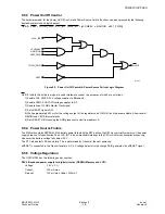
This section describes the Power Supply Unit (PSU) used on the GD30/GD50 Main PCB and the method by which it is
controlled. The Battery life during GSM 1800 operation benefits from lower transmit power and higher PA efficiency and is
therefore more efficient than when operating in GSM 900.
This section has detailed information on:
1.
An overview of the circuit functionality.
2.
Powering-up the phone.
3.
Powering-down the phone.
4.
Power management.
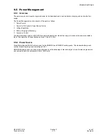
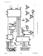
9.2 Overview
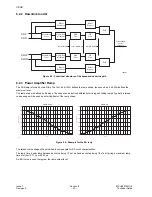
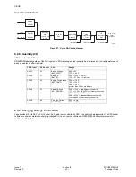
The logic circuit uses three separate power supplies as follows:
1.
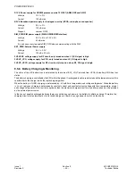
2.8 Volts supply is used for the main power supply, 2V8 provides power to the digital part of the baseband circuit (Gemini,
Memory and LCD). A2V8 is used to power the analogue part of the baseband circuit (Vega and voice memo).
2.
1.8 Volts is provided to power internal blocks within the Gemini (ARM, DSP, ASIC).
3.
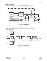
5.0 Volts (SIM_PWR) is provided to power the SIM and the SIM interface. This is enabled only when it is necessary to
communicate with the SIM.
The RF circuit uses three power supplies each provided by a separate 2.8 Volt regulator within U401. They are:
VSRF and VS_VCO which are present when the LO_EN signal is present.
VS_RF and VS_VXCO which are present when the signal RF_ON is present.
The power amplifiers are powered directly from the battery VBAT.
9.3 Power-up
9.3.1 Power Modes
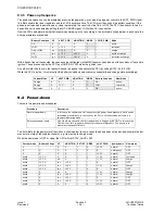
The power-up procedure has two phases. If an initial check to see if the battery is in good condition is successful, the second
phase determines the source of the power-up request, key press, external power, accessory, etc. and acts accordingly.
The phone can be defined as powered-on whenever the linear regulators are active. It is not always obvious to the user that
the phone is powered-on as it may be in one of four modes:
9.3.2 Battery Condition
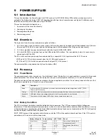
The CPU must check the battery condition before deciding to power-up. The CPU can measure battery voltage and
temperature. If the battery temperature measurement is invalid, a non-standard battery has been fitted, the battery is missing
or the whole phone is operating far outside its specified temperature range, the phone is not powered-up. The CPU will regularly
monitor the battery condition while the phone is on.
If EXT_PWR is present, the regulators will be forced on and the CPU will be unable to deactivate them. If the CPU wants to
power-down, all it can do is to enter sleep mode.
Mode
Description
Sleep
In this mode the CPU has been prevented from deactivating the linear regulators by EXT_PWR.
There is no CPU activity.
Charge
The CPU is alive but may perform
only
battery charging functions and monitor the power key.
Restricted
LEDs light, beeps, can charge battery etc. but it is
not
permitted to use the radio.
Active
The mobile is fully functional; LEDs light, beeps, search for network etc.
Battery Voltage (V)
Temp. reading
nEXT_PWR
Result
X (don't care)
invalid
0.5 V
Power-down (battery fault)
X
invalid
1.2 V
Sleep (battery fault)
<3.0
X
<0.5 V
Power-down (low battery)
<3.5
valid
1.2 V
LOW
>3.5
valid
X
OK

