

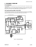

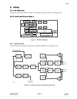

BASEBAND OVERVIEW
Issue 1
Section 6
MCUK991001G8
Revision 0
– 22 –
Technical Guide
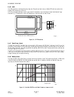
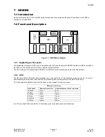
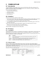
6.2.6 LCD
The LCD assembly is a sub-assembly comprising the LCD glass and driver chip on a flexible PCB with connection to the
Keypad PCB via zebra strip connectors.
A 96 x 58 pixel graphical display is used to give maximum information. It can also display Chinese characters and large
characters, e.g., 12 characters x 2 lines or 16 characters x 3 lines, both with two lines of icons.
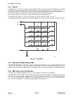
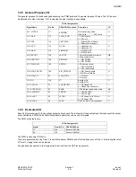
Figure 6.4: LCD Dimensions
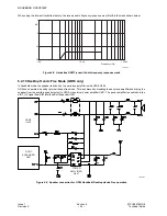
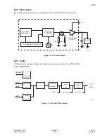
6.2.7 Real Time Clock
The Real Time Clock (RTC) and Alarm function is provided by U505 running at 32,768 MHz. It interfaces to the CPU via a four
serial lines: CE (chip enable), SCLK (serial clock), SI (serial input) and SO (serial output). To maintain power to the clock when
the main battery is removed, a small rechargeable back-up battery (VBACKUP) is used. This power source also provides power
back-up for data held in the SRAM.
The RTC can be calibrated using a high-precision oscillation adjustment function. This gives a maximum adjustment range of
±189.2 ppm in increments of 3 ppm. Addition functions of the RTC are date, alarm, periodic interrupt, 32 kHz output, supply
voltage monitoring and oscillation halt sensing.
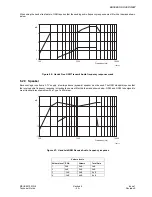
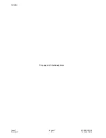
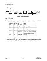
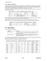
6.2.8 Microphone
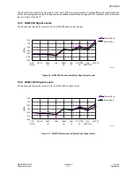
To achieve optimum audio performance, a microphone with two capacitors is used. This provides suppression to TDMA noise
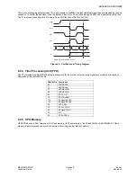
at both 900 MHz and 1800 MHz. The GSM standard requires that when in handheld mode the sending audio frequency
response must fit within the mask shown below.
Figure 6.5: Handheld GSM Transmit Audio frequency response mask
22.02
28.3 min
0.01
0.36
View Area
Effective Area
0.01
0.30
10168-1
28.78
33.6 min
Dimensions are in millimetres (mm)
dB
5
-10
0
-5
-15
100
1000
10000
Frequency (Hz)
10069-1


