TRANSMITTER
Issue 1
Section 4
MCUK991001G8
Revision 0
– 14 –
Technical Guide
4.3 Functional Description
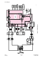
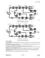
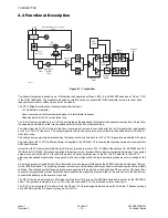
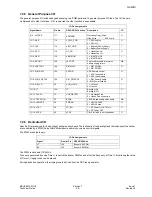
Figure 4.1: Transmitter
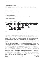
The transmitter design is based on an IQ Modulator and operates at Class 4 (2W) in the GSM 900 band and at Class 1 (1W)
in the GSM 1800 band. The architecture has been carefully chosen to enable the GSM transmitter noise in receiver band
requirements to be met without the need for a duplexer.
The RF IC Bright2 provides the following transmitter functions:
I, Q Quadrature modulator
Down conversion mixer for modulated signal to intermediate frequency
Phase detector for the PLL modulation loop.
The IF LO signal generated by the IF VCO is modulated by the baseband I,Q signals in the quadrature modulator. Output from
the quadrature modulator is fed into the phase detector for the PLL modulation loop.
The output from the Tx VCO is fed into the down conversion mixer and is converted with the 1st LO signal which is generated
by the 1st VCO to IF frequency. The output signal from the down conversion mixer is fed into the phase detector for the PLL
modulation loop.
The charge pump output signal produced by the phase detector is fed back to the Tx VCO to generate modulated RF output.
The output from the Tx VCO is filtered before it is applied to the PA driver. This ensures that spurious emissions are well within
GSM specifications.
Output from the PA driver is amplified by the PA to any required level up to PL5 (33 dBm at the antenna) for GSM 900 and PL0
(30 dBm) for GSM 1800. PA output is applied to the antenna via a low-pass filter to remove unwanted harmonics. The coupled
outputs are used by the APC-IC to control the gain, and hence output power, of the PA. The RF detector in the APC-IC
produces a baseband output which is compared with a control signal from the logic section to produce a control voltage for the
PA.
A discrete diplexer is used after the PA buffer which provides low pass filtering for the 900 MHz band and high pass filtering
for the 1800 MHz band. The switching between the receiver and the transmitter for any band is achieved by means of pin diode
switches. The antenna ports of these switches are connected to the antenna or the hands free RF connector. The hands free
connector incorporates a mechanical switch which enables the signal to be routed either to the antenna or to the hands free
connector depending on the operation required.
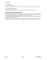
The RF LO is also a dual modular VCO which contains two VCOs, one for the 900 MHz band and the other for the 1800 MHz
band. The operation is similar to the Tx VCO in that the required RF VCO is switched by two control lines.
The IF VCO is a discrete VCO module. Both the RF and IF LOs are designed around a dual PLL with the IF frequency range
up to 600 MHz and the RF frequency range up to 2 GHz.
I
Q
Modulator
Loop
Filter
Phase
Detector
Diplexer
S701
Coupler
E801
900
1800
900 MHz
1800 MHz
Dual Band
Tx VCO
U702
Coupler
E800
Dual Band PA
U801
Exciter
U802
Antenna
+ Sw.
DC
Mixer
Dual Band Receiver
(PART)
U701
10153-1
APC
U800


