background image

58

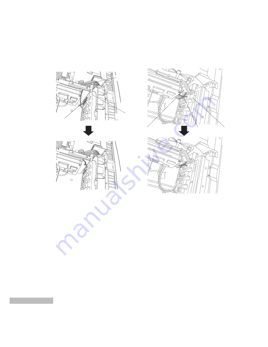
For a MICRON PC mini tower type

Board spacer

Guide rail

twist-tab wire

Pass the twist-tab wire through a hole of the guide rails as shown above.
Use the twist-tab wire to secure the board spacer to the guide rails inside the computer.
Twist the twist-tab wire and secure it properly.
Check that the board spacer has been secured properly.

Connect the ground wire to the computer's chassis only when the metal type of board spacer is supplied.
(Refer to page 11)

Board spacer (metal type)

Board spacer (plastic type)

Guide rail

Board spacer

twist-tab wire

Summary of Contents for AY-RP500

Page 1: ...Before attempting to connect or operate this product please read these instructions completely Nonlinear Editing System Control Panel Kit AY RP500 ...

Page 2: ...n equi lateral triangle is intended to alert the user to the presence of important operating and maintenance servicing instructions in the literature accompa nying the appliance The serial number of this product may be found on the bottom of the unit You should note the serial number of this unit in the space provided and retain this book as a perma nent record of your purchase to aid identificati...

Page 3: ...nnels This system can playback video on two channels with excellent image quality DVCPRO system The DVCPRO system is used for video compression and decompression A user interface suited for video production Because icons are used for stills representing each scene editing is more intuitive and efficient in com parison with earlier VCR editing controllers The video editing process can be conducted ...

Page 4: ...RECAUTIONS Do not expose the main unit and JOGPAD to rain or moisture and do not try to operate the equipment in wet areas Do not operate the main unit and JOG PAD if it becomes wet Do not attempt to disassemble the main unit or JOG PAD In order to prevent electric shock do not remove screws or covers There are no user serviceable parts inside Do take immediate action if ever the main unit or JOGP...

Page 5: ... connections This connector is used to connect the hard disk box via a special cable 2 Channel B Ch B connector for external connections This connector is used to connect the hard disk box via a special cable 3 Channel A Ch A connector for internal connections This connector is used to connect the hard disk housed in the personal computer via a flat cable accessory with SCSI board 4 Channel B Ch B...

Page 6: ...essory with the time code input and output on a VCR etc and with equipment that inputs an external signal for synched composites horizontal sync only Time code input and output This connector is used to connect with the time code input and output on a VCR etc Make this connec tion only if the VCR has a time code signal LTC out put The time code output is not a loop through of the signal that was i...

Page 7: ...eginning or end of a sequence 7 MARK OUT Sets or cancels the ending mark SHIFT MARK OUT Selects the grip of the OUT point 8 MARK IN Sets or cancels the starting mark SHIFT MARK IN Selects the grip of the IN point 9 PLAY STOP Plays back or stops SHIFT PLAY STOP Plays back between the starting and ending marks 10 Shuttle Ring Plays back video and audio forward clockwise or in reverse counterclockwis...

Page 8: ...SC monitor etc This cable is provided with the video compression board VCR JOGPAD cable E8 163J601 This cable connects the JOG board with the JOGPAD and the DVCPRO VCR RS422 This cable is provided with the JOG board LTC REF cable E9 165J600 This cable connects the JOG board with the DVCPRO VCR Time code IN OUT and the external sync input This cable is provided with the JOG board SCSI cable ACK M W...

Page 9: ... Y U I O P q w e r t Label S VIDEO IN R Y R IN B Y B IN CV CS IN Y G IN R AUDIO IN L AUDIO IN S VIDEO OUT L AUDIO OUT R AUDIO OUT CV CS OUT Y G OUT B Y B OUT R Y R OUT KEY OUT REF IN Connector S connector BNC BNC BNC BNC XLR XLR S connector XLR XLR BNC BNC BNC BNC BNC BNC D sub 60 pin Signal name YC input Component R Y input Component B Y input Composite input Component Y input Audio R channel inp...

Page 10: ...ol connector on VCR etc VCR etc JOG board JOGPAD Cable color Red Green Blue Black Label Ref IN Ref OUT LTC IN LTC OUT Signal name External sync input Ref IN loop through LTC input LTC output LTC REF connector plug No Q W E R T Plug shape BNC BNC BNC BNC Mini DIN 9 pin JOG board q w r e t ...

Page 11: ... 1 gigabyte of memory for the system drive where Windows NT will be installed 2 Turn off the computer 3 Open the case of the computer For details on how to do so refer to the instruction manual that was pro vided with the computer 4 Confirm which PCI slot the white connector on the motherboard the video card is installed in If the video card is already in the PCI slot that is the far thest from th...

Page 12: ...the longest board among the TARGA DV2000 boards Refer to the diagram below The board spacer comes in two types metal and plastic but only one type is enclosed with the unit 1 Board spacer metal type BIOS Setup 1 This procedure sets up the motherboard BIOS 2 Open the BIOS setup screen The method of calling up the BIOS setting screen varies depending on the computer Refer to the user s manual of the...

Page 13: ...ple The actual con nection locations may differ depending on the model of computer used Connect the ground wire to the computer s chassis metal portion only when the metal type of board spacer is supplied Then use the twist tab wire to secure the board spacer to the guide rails inside the computer The installation of the AY PB500 board TARGA DV2000 board will differ depending on the computer used ...

Page 14: ... remove the CD ROM from which the driver was installed 11 When Windows NT has restarted click From Programs in the Start Menu click Administrative Tools p Windows NT Diagnostics The program starts up Start Finish Next Next Next Next 12 5 Connect the CA 206 cable that was provided with the TARGA DV2000 board Plug the connector labelled TARGA DV2000 into the connector on the TARGA DV2000 board plug ...

Page 15: ...e The drivers were successfully installed appears Click OK OK OK Have Disk Change Display Types Start OK 8 Click in Display Types 9 Click in Screen Properties 10 The message You must restart your computer appears Click 11 Windows NT starts up When the Control Panel opens close it When the message A new graphics driver has been installed appears click 12 Click and drag the mark on the frame of the ...

Page 16: ...turer and the SCSI adapter list appear Select Adaptec for the manufacturer and AHA 294x AHA 394x or AIC 78xx PCI SCSI con troller for the adapter and click Here the Windows NT CD ROM is required so load it and click The WIndows NT CD ROM window opens This is not needed so click the on the upper right of the window to close it 10 Specify the directory of the driver For example if the CD ROM drive i...

Page 17: ...S Support for Int13h Extensions Enabled Support for Ultra SCSI Speed Disabled Setting the baud rate of the SCSI board Set the SCSI baud rate of the SCSI board Check the model number of the board used and set the rate by following the procedure given When AHA 3940UWD is the SCSI board used 1 Power On 2 Appear next comment when Boot Up Adaptec AHA 3940U 3940UW BIOS v1 xx c 199x Adaptec Inc ALL Right...

Page 18: ...nel of the one to be configured and press Enter F5 Toggle color Monochrome 00 0E A 00 0E B Bus Device channel AHA 3940AU AUW AUWD at Bus 00h Device 0Eh Channel A Would you like to configure the host adapter or run the SCSI disk utilities Select the option and press Enter Press F5 to switch between color and monochrome modes Configure View Host Adapter Settings SCSI Disk Utilities Options 9 Press E...

Page 19: ...es yes yes yes yes yes Options Listed Below Have NO EFFECT if the BIOS is Disabled Send Start Unit Command no no no no no no no no BIOS Multiple LUN support no no no no no no no no Include in BIOS Scan yes yes yes yes yes yes yes yes SCSI device ID 8 9 10 11 12 13 14 15 Initiate Sync Negotiation yes yes yes yes yes yes yes yes Maximum Sync Transfer Rate 20 0 20 0 20 0 20 0 20 0 20 0 20 0 20 0 Enab...

Page 20: ...G board uses IRQ and I O port exclu sively be certain to set a number that are not used by any other device Confirm settings of other devices using the Windows NT diagnostic program page 19 Note on IRQ Settings 5 and 7 are recommended If 5 and 7 are being used by another device set either 3 or 4 Because 3 and 4 are nor mally used for serial ports COM1 COM2 either 3 or 4 must be disabled in the BIO...

Page 21: ...l appear Select the same values as the jumper pin settings When installation ends the Setup Complete window appears Select Yes I want to restart my computer now When this is selected is displayed Click The computer will restart 8 When Windows NT has restarted click From Programs in the Start Menu click Administrative Tools p Windows NT Diagnostics The program starts up Start Finish 9 The Windows N...

Page 22: ...w Insert jumpers Note When two hard disks are installed make their set tings for the SCSI IDs and terminations the same Installing the hard disk Note Only SCSI hard disk drives with a capacity of 2G or 4G can be installed inside the personal computer Operation is not guaranteed if a hard disk with a larger capacity for example 9G is installed To install a hard disk with a larger capacity use the h...

Page 23: ...d disk drive 1 Take off the front panel of the personal computer The assembly diagram shown below is intended as an example The actual connection locations may differ depending on the model of computer used 2 Remove the brackets of the expansion bay The assembly diagram shown below is intended as an example The actual connection locations may differ depending on the model of computer used Front Pa...

Page 24: ...r depending on the model of computer used 4 Use the flat cable 68 pin Wide SCSI provided with the SCSI board Connect one end to the connector on the hard disk and connect the other end to the connector on the SCSI board Refer to the diagram below The assembly diagram shown below is intended as an example The actual connection locations may differ depending on the model of computer used When there ...

Page 25: ... boxes two hard disks per box and two internal hard disks totalling eight When all hard disks are housed in optional hard disk box Five optional hard disk boxes two hard disks per box totalling ten When installing a hard disk in a hard disk box optional Installing a hard disk A hard disk with a capacity of 2G 4G or 9G can be installed in a hard disk box For details on how to install a hard disk in...

Page 26: ...34371W made by SEAGATE is connected to ID 1 If the devices actually connected are at variance with what is listed a wrong connection SCSI ID set ting error terminal setting error or defective hard disk may be to blame Press ESC key to exit First check the connections and the SCSI ID and terminal settings If the message remains a defec tive hard disk may be to blame If what is listed matches with t...

Page 27: ...he option and press Enter Press F5 to switch between color and monochrome modes Configure View Host Adapter Settings SCSI Disk Utilities Options 8 Appear the following confirmation message Move the cursor select Yes and press Enter key Disk check now commences If this check discovers trouble in the disk media a message prompting the user to proceed with re allo cation appears When Yes is selected ...

Page 28: ...Disk and press Enter SCSI ID 0 No device SCSI ID 1 SEAGATE ST34371W SCSI ID 2 No device SCSI ID 3 No device SCSI ID 4 No device SCSI ID 5 No device SCSI ID 6 No device SCSI ID 7 AHA 3940 Ultra Ultra w SCSI ID 8 No device SCSI ID 9 No device SCSI ID 10 No device SCSI ID 11 No device SCSI ID 12 No device SCSI ID 13 No device SCSI ID 14 No device SCSI ID 15 No device Format Disk Verify Disk Media 8 A...

Page 29: ... disk CD ROM No difference whether inside or outside the com puter Start Note When setting up the disk if the audio or video hard disk display is for a logical drive displayed in blue rather than the primary partition dis played in dark blue the procedure described below must be performed in order to change to the primary partition 1 Click on select the logical drive area dis played in blue 2 Clic...

Page 30: ...ick Create in Partition 22 The screen message will prompt you for the size of the partition to be created Do not modify anything but just click OK Yes OK Close OK OK Start When two SCSI hard disks are for video and one SCSI hard disk is for audio 1 Disk 0 is the IDE drive and disks 1 through 3 are the SCSI hard disks Two of the SCSI hard disks are for video and one is for audio They are in the ord...

Page 31: ...select it 38 On the menu bar above the window click Create in Partition Yes Close OK OK Start OK Yes 39 The screen message will prompt you for the size of the partition to be created Do not modify anything but just click When the confirmation mes sage is displayed click The selected area will have the message Unformatted 40 In Partition on the menu bar click Commit Changes Now 41 At the message Do...

Page 32: ...ing Windows NT so that separate areas can be made for system use and audio use Otherwise operation cannot be guaran teed When creating the path leave at least 1G bytes for the system area area for installing Windows NT 2 The area other than C drive of disk 0 will be for audio If this area is not indicated in crosshatch display carry out the following procedure 1 Click this area to select it Once s...

Page 33: ...successfully appears Click 11 The message of the unformatted area of disk 0 changes to Unknown 12 Click the Unknown area of the disk to select it 13 In Tools on the menu bar click Format 14 The format window opens Click of File system and select NTFS 15 Click the format option Quick format to check it with the mark 16 Click The warning display appears but click 17 When the message Format complete ...

Page 34: ...A loop cable CA 206 to the TARGA board and to the VGA board and connect the female end to the personal computer monitor cable The monitor requirements are as follows Resolution 1152 x 870 max Horizontal scanning frequency 68 025kHz max Vertical sync frequency 75Hz max SYSTEM CONNECTION Keyboard connecting cable Keyboard Computer rear VGA loop cable 15 pins CA 206 MONITOR VGA board Personal compute...

Page 35: ... pin JOGPAD connector on the JOG board Use the screws to secure the cable connector to the connector on the rear of the JOGPAD Be sure to cut the power before connecting cables OPEN OK UNDO SHIFT TRIM M ODE DIVIDE DELETE ZOOM GOTO PL AY S TO P MARK IN MARK OUT JOG board JOGPAD JOGPAD VCR JOGPAD cable Computer rear D sub 9 pin Mini DIN 8 pin ...

Page 36: ...to Blackburst Genlock Input if REF IN is input to the TARGA board For details on setup read the Special section in the software manual RS422 LTC REF L R S VIDEO OUT R Y R OUT B Y B OUT Y G OUT R AUDIO OUT L AUDIO OUT R Y R IN B Y B IN Y G IN R AUDIO IN L AUDIO IN REF IN LTC OUT LTC IN REF IN TARGA board JOG board LTC REF cable RS422 1 RS422 2 Audio output EE output Commercial VCR Reference input S...

Page 37: ...RS422 Audio output EE output Commercial VCR Reference input Video output monitor Video output Speakers with built in amplifiers Analog I O cable Computer rear VCR JOGPAD cable S VIDEO OUT R Y R OUT B Y B OUT Y G OUT R AUDIO OUT L AUDIO OUT R Y R IN B Y B IN Y G IN R AUDIO IN L AUDIO IN CV CS OUT LTC OUT LTC IN REF IN REF OUT JOG board TARGA board LTC REF L R SCSI board VGA board Relay Plug ...

Page 38: ...e If a DVCPRO series VCR is used the EE output from the VCR lags the input signal by about five frames Coaxial relay plug REF OUT cable Termination S VHS VCR No RS422 control Set Genlock Input Control to Disabled Video output monitor R AUDIO OUT L AUDIO OUT S VIDEO OUT S VIDEO IN R AUDIO IN L AUDIO IN XLR3 RCA pin conversion cable XLR3 RCA pin conversion cable TARGA board JOG board Analog I O Cabl...

Page 39: ...Serial Digital Interface SDI When connecting a video cassette recorder designed for commercial applications As in the figure below Genlock Input Control is set to Disable TAPE EE switch is set to TAPE in VCR RS422 LTC REF L R TARGA board JOG board LTC REF cable RS422 1 RS422 2 Commercial VCR Video output monitor Speakers with built in amplifiers I O cable Computer rear VCR JOGPAD cable ...

Page 40: ...e hard disk drive could be lost and the hard disk drive itself could be damaged Note When using an external hard disk unit do not move the unit for at least 30 seconds after turn ing off the power for the hard disk unit The motor in the hard disk unit may still rotate for up to 30 seconds after the power is turned off if the hard disk unit is moved while the motor is still rotating data on the har...

Page 41: ...tor Setting Up the Virtual Memory This procedure sets up the virtual memory to operate the application program DVEdit Setting Drive C Initial Size 300MB Maximum Size 400MB Do not expand the virtual memory in a wrong drive Otherwise it is not assured that the DVEdit works properly 1 Open the Control Panel 2 Double click the icon System 3 Click the button Change LOADING SOFTWARE PACKAGE ...

Page 42: ... 4 Click C 5 Enter 300 in the box for initial size and 400 in the box for maximum size 6 Click the button Confirm that the top window shows 300 400 Then click on this panel 7 Click and restart Yes OK Set ...

Page 43: ...V2000 SDX For SDI Voyager 2 select TARGA DV2000 SDX V2 When the type is selected is displayed Refer to Appendix The type of the SDI board about the type of the board 9 The A V Hard Disk Information window appears Enter the number of hard disk drives for video use To select two hard disk drives for video use enter 2 at the Drives prompt To select four hard disk drives for video use enter 4 at the D...

Page 44: ...n installation ends the Setup Complete window appears Select Yes I want to restart my computer now When this is selected is displayed Click The computer will restart 19 The Shortcut DVEdit is created Finish Next Next Next Next Next Installing Fonts 1 Open the Control Panel and double click the Fonts icon The Fonts panel appears 2 Insert the software package CD ROM into the CD ROM drive 3 Click Ins...

Page 45: ...ading the version If the new software is installed after uninstalling the existing software all the data will be erased for a new setup Precautions The following two cases can be considered in installing the new software in DVEdit Carefully replace the existing software by observing the version up procedures for each of the three cases described in the following section 1 Erasing data from DVEdit ...

Page 46: ...river and that of the DVEdit software If they are the same neither needs to be replaced If the Targa driver version is the same skip items 3 and 4 and proceed to items 5 and 6 Description of Targa driver replacement Items 4 and 5 Description of software replacement Items 6 and 7 4 Uninstalling the Old Targa Driver a Select Program Targa DV2000 and uninstall Targa DV2000 from Start This starts unin...

Page 47: ...ing the Targa driver Insert a CD ROM into the CD ROM drive The case where the CD ROM drive is d is described below Move the cursor to the Run command in the Start menu and click the command The Run window will be displayed Type the command d Targa disk1 setup exe in the Open field of the Run window and click the button This starts the Targa installer so start installing as instructed on the panel ...

Page 48: ...g the mark on the frame of the desktop area in Screen Properties to adjust it for the resolution of 1152 x 870 pixels Here confirm that the font size is small and that the Refresh Frequency is 75 Hz n Click and click to enter test mode The test screen appears o If the test screen is displayed correctly click p Click in Display Properties to close this screen The resolution will change OK Yes OK Te...

Page 49: ...n the panel The subsequent operations are the same as installing DVEdit for the first time Start installing according to the instructions on the panel shown After install is completed the panel asks whether or not to restart so restart as shown on the panel When the icon DVEdit on the deskstop is double clicked after restart the new version of DVEdit is ready for use OK Yes Not Erasing Data from D...

Page 50: ...arga driver and that of the DVEdit software If they are the same neither needs to be replaced If the Targa driver version is the same skip items 4 and 5 and proceed to items 6 Description of Targa driver replacement Items 4 and 5 Description of software replacement Items 6 4 Uninstalling the Old Targa Driver a Select Program Targa DV2000 and Uninstall Targa DV2000 from Start This starts uninstalli...

Page 51: ...ling the Targa driver Insert a CD ROM into the CD ROM drive The case where the CD ROM drive is d is described below Move the cursor to the Run command in the Start menu and click the command The Run window will be displayed Type the command d Targa disk1 setup exe in the Open field of the Run window and click the button This starts the Targa installer so start installing as instructed on the panel...

Page 52: ...equency is 75 Hz n Click and click to enter test mode The test screen appears o If the test screen is displayed correctly click p Click in Display Properties to close this screen The resolution will change OK Yes OK Test OK Yes Close Close OK OK OK Have Disk Change 6 Installing new DVEdit Insert a CD ROM into the CD ROM drive The case where the CD ROM drive is d is described below Move the cursor ...

Page 53: ...dit Shortcut 3 After the application starts up the initial screen Tool Box BIN Manager and BIN Window is displayed on the per sonal computer s monitor Computer Display is shown below BIN Manager BIN Window 1 Click on the Tool Box 2 If you wish to exit click application shuts down OK Exit 3 Quit Windows NT Once the message It is now safe to turn off your computer appears turn off the power switch f...

Page 54: ... and select the tab Performance Click the button one of the virtual memory items to open the virtual memory panel then check the following a Is the drive set in the paging file C b Is the initial size of the paging file 300 MB c Is the maximum size of the paging file 400 MB Change 1 Board Installation Check a Is the Targa board installed in the first slot from the CPU b Is the SCSI board installed...

Page 55: ...r it with Font Setup on the Special panel h Has the device been set up Set up Reference VTR Type Input Output Type etc with Device Setup on the Special panel After checking all of the above confirm again that the installation procedures have been completed Then check on the Windows NT Diagnostic Program panel that IRQ assignments have been properly made on the panel shown below IRQ etc may not alw...

Page 56: ... left on the first line from the top 1 from the left from the second line from the top 1 from the left on the third line from the top 1 from the left on the fourth line from the top Title settings can be made using the sequence editor and can be reproduced as per the settings Video key settings can be made using the sequence editor and can be reproduced as per the settings Audio Modify Level chann...

Page 57: ...55 ...

Page 58: ...secure the board spacer to the guide rails inside the computer For a GATEWAY PC tower type APPENDIX Use the twist tab wire to secure the board spacer to the guide rails inside the computer Twist the twist tab wire and secure it properly Check that the board spacer has been secured properly Connect the ground wire to the computer s chassis only when the metal type of board spacer is supplied Refer ...

Page 59: ...wist tab wire to secure the board spacer to the guide rails inside the computer Twist the twist tab wire and secure it properly Check that the board spacer has been secured properly Connect the ground wire to the computer s chassis only when the metal type of board spacer is supplied Refer to page 11 Guide rail twist tab wire Guide rail twist tab wire ...

Page 60: ... secure the board spacer to the guide rails inside the computer Twist the twist tab wire and secure it properly Check that the board spacer has been secured properly Connect the ground wire to the computer s chassis only when the metal type of board spacer is supplied Refer to page 11 Board spacer metal type Board spacer plastic type Guide rail Board spacer twist tab wire ...

Page 61: ...nsulating sheet SDI board Install the proper software for each type of the SDI board Type 1 has no analog audio monitor Select it for installing TARGA DV2000 SDX Type 2 has analog audio monitor Select it for installing TARGA DV2000 SDX V2 The type of the SDI board Video compression board The SDI board comes in two types Type 1 You can find the LSI printed GENNUM turning over the insulating sheet T...

Page 62: ...rminal Component Y 1 0 V p p 75 Ω BNC PB PR 0 525 V p p or 0 756 V p p selectable 0 setup 75 Ω BNC PB PR 0 486 V p p or 0 7 V p p selectable 7 5 setup 75 Ω BNC Synchronization Gen Lock Input 1 0 V p p 75 Ω BNC x1 Audio Input 1 source 0 dBu 20 kΩ balanced XLR connector Audio Output 1 output 0 dBu Low Impedance balanced XLR connector VGA Output D SUB 15pin Video Output 1 0 V p p 75 Ω Horizontal Freq...

Page 63: ...5 V DC 12 V Power Consumption 2 1 W Ambient Operating Temperature 5 C 35 C Ambient Operating Humidity 10 90 Weight JOG Board 0 3 kg JOGPAD 1 15 kg Supplied Accessory JOGPAD Special Cable x 1 RS422 Special Cable x 2 LTC REF Cable x 1 Termination x 1 Board spacer x 1 Hard disk Fittings x 4 Screw x 16 AY PB500 Power Supply 5 V DC 12 V Power Consumption 37 7 W Ambient Operating Temperature 5 C 35 C Am...

Page 64: ...c New England Southeast Region Central Region WESTERN ZONE Dallas Region No CA Northwest Region Government Marketing Department 3330 Cahuenga Blvd W Los Angeles CA 90068 323 436 3500 One Panasonic Way 4E 7 Secaucus NJ 07094 201 348 7621 One Panasonic Way 4E 7 Secaucus NJ 07094 201 348 7621 1225 Northbrook Parkway Ste 1 160 Suwanee GA 30024 770 338 6845 1707 N Randall Road E1 C 1 Elgin IL 60123 847...

Reviews: