26
Operation
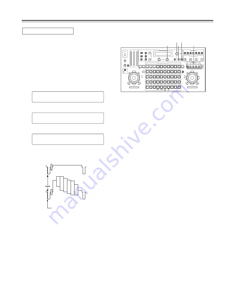
1. Select the pan-tilt head system using the
CONTROL/PREVIEW MONITOR OUT SEL button.
2. Supply the genlock signal to the G/L IN connector on the
main unit, and connect a dual-trace oscilloscope to the
loop-through connector and VIDEO/Y OUT connector on
the main unit corresponding to the pan-tilt head system
currently selected.
3. Press the MENU button, turn the menu setting control
(main), and set it so that the G/L SETTING item appears
at the top of the LCD panel.
4. Press the OK button.
The following item appears on the LCD panel.
5. Turn the menu setting control (main), and set it so that
the following item appears on the LCD panel.
6. Using the menu setting control (R), align the horizontal
phase of the video signal waveforms on the oscilloscope
and external sync signal waveforms.
H
H
P
PH
HA
AS
SE
E
±
±0
0
C
CA
AB
BL
LE
E
L
LE
EN
NG
GT
TH
H
S
SH
HO
OR
RT
T
G
G/
/L
L
S
SE
ET
TT
TI
IN
NG
G
n
O
OK
K
K
Ke
ey
y
Horizontal phase adjustment
External sync
signal
Video signal
Align the horizontal phase.
7. Select the next pan-tilt head system using the
CONTROL/PREVIEW MONITOR OUT SEL button, and
continue adjusting the horizontal phase in each system
concerned.
CONTROL/PREVIEW MONITOR OUT SEL
AUX
1
2
3
4
5
TALLY
TRACING MEMORY
LAMP
MENU
LIMIT
OFF
LIMIT
ON
FULL
EMPTY
OK
LCD
CONTRAST
CAMERA
CONTROL
START
POINT
R/B
GAIN/PED
WHITE
BAL
AWC
GAIN
MODE
CLOSE
WIDE
NEAR
DATA SET
TR/PSET M.LOCK
MEMORY
IRIS
IRIS
IRIS
OPEN
ZOOM
TELE
FOCUS
FAR
CALL
INCOM
LEVEL
FOCUS
OPEN
FAR
TELE
OFF
ON
OPERATE
WIDE
ZOOM/FOCUS/IRIS
ABC
ATW
A
B
NG
OK
START/STOP
RESTORE
RESET
DEF
WIP
H/F
EXT
ND
OPTION
PAN/TILT SET
CAMERA CONTROL
TRACING/PRESET MEMORY
IRIS
SPEED
PRIORITY
FOCUS
BAR
CAM
TR
PSET
LOW
HIGH
AUTO
MANU
AUTO
MANU
LOCK
1
2
3
4
5
6
7
8
9
10
11
12
13
14
15
16
17
18
19
20
21
22
23
24
25
26
27
28
29
130
31
32
33
34
35
36
37
38
39
40
41
42
43
44
45
46
47
48
49
50
DOWN
PA N / T I LT / F O C U S / I R I S
U P
L
R
CLOSE
NEAR
OPEN
FAR
CLOSE
NEAR
3
6
3•5 4
1
Summary of Contents for AWRP605P - MULTI FUNCTION CONTROLLER
Page 45: ......


