18
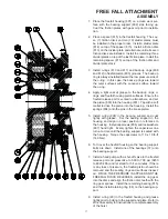
209
201
208
210
207
202
204
205
203
206
BRAKE CYLINDER
DISASSEMBLY
1. A hydraulic press or spring compressor tool is re-
quired to disassemble the brake subassembly. Place
the brake subassembly on the press with the primary
housing cover (201) down. Place a heavy steel bar
across the large diameter of the pressure plate (210)
and compress the springs until spring force is removed
from the retaining ring (209). Remove the retaining
ring with retaining ring pliers. Slowly release the press
force on the pressure plate.
2. Remove the pressure plate (210), spring separator
(208), and springs (207).
3. Remove the brake piston (202) from the primary hous-
ing cover (201). Remove the o-rings and back-up
rings from the brake piston and discard (items 203,
204, 205, and 206).
Clean and Inspect
1. Thoroughly clean and inspect all parts. Check seal-
ing surfaces on the primary housing cover and brake
piston. Ensure the brake release port is clean and free
of debris.
2. Place brake friction disc on a fl at surface and check
for distortion with a straight edge. Friction material
should appear even across the entire surface with the
groove pattern visible. Replace friction discs or divider
plates if distorted, burned, wear is uneven, or splines
are worn to a point. Minimum thickness of friction ma-
terial is .160 in. (4 mm.) measured at the center of the
friction surface
3. Check brake spring free length. Minimum free length
is 2.910 in. (73.9 mm.) If it is required by measurement
to replace one spring, you must replace all springs to
maintain consistent spring force distribution.


