19
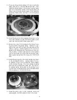
5. Install the spring separator (208). The spring spacer
seats on the piston. Install the springs (207) in the
spring separator and space evenly. There are 24
holes in the spring spacer, so with 12 springs put a
spring in every other hole. Align the empty holes with
the fi ll and drain holes as shown in the photograph
below.
6. Install the pressure plate (210) onto the springs with
the fl at surface toward the springs.
7. Place a heavy steel bar across the outside diameter
of the pressure plate. Use the press to compress the
springs until there is clearance to install the retaining
ring (209) into the groove in the piston. Install the re-
taining ring and make certain it is seated securely BE-
FORE releasing press or spring compressor. Use a
hammer and punch to seat the retaining ring as shown
below.
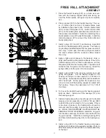
1. A hydraulic press or spring compressor tool is required
to assemble the brake subassembly. Place the brake
housing cover (201) on a clean work surface with the
motor side up and space it at least 2-inches (50 mm.)
off the table with wood or metal blocks. This gives
clearance for the brake piston (202) installation.
2. Install the o-rings (204, 205) and back-up rings (203,
206) in the piston grooves. The back-up ring is always
to the low pressure side of the o-ring, which is the out-
side surface of the piston for this part as shown in the
illustration below. The concave side of the back-up
ring provides a seat for the o-ring. Lightly grease the
o-rings and back-up rings after installation on the pis-
ton.
3. Apply grease to the housing cover at the piston seat-
ing surface and install the brake piston in the primary
housing cover (201) – if necessary, tap lightly to seat
in the housing cover.
4. Place the primary housing cover on the press table
with the motor side down. Place a spacer under the
piston to keep it raised in the housing cover.
BRAKE CYLINDER
ASSEMBLY
PRESSURE SIGNAL
BACKUP RING
#203
BACKUP RING
#206
O-RING
#205
O-RING
#204
Fill or Drain Hole


