Paccar Winch Gearmatic GH30B Service And Maintenance Manual Download Page 9

9

The gear oil should be changed whenever the ambient 
temperature changes signifi cantly and an oil from a dif-
ferent viscosity range would be more appropriate. Our 
tests indicate that excessively heavy or thick gear oil may 
contribute to intermittent brake slippage. Make certain the 
gear oil viscosity used in your hoist is correct for your pre-
vailing ambient temperature.

NOTE: If the oil sampling/analysis has not been performed 
as required, tear-down inspections will be required. Refer 
to Hoist Disassembly section of this manual.

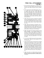
The GH30B-FF hoist has an oil seal which separates the 
primary housing gear oil from the free-fall housing gear oil. 
The free-fall end is fi lled to the center of the sight gauge 
shown on the drawing. The motor end is fi lled until oil 
drains out of the level plug shown on the drawing. Wire 
rope must be spooled off the drum to allow access to the 

drum drain plug. Rotate the drum until the drain plug is at 
the lowest point.

To change the gear oil, remove the drain plugs shown on 
the drawings below from each end of the hoist and the 
drum and collect a sample from each housing for oil analy-
sis. Removing the vent plugs will speed the oil drain. When 
the oil has drained, install the drain plugs.

Refi ll the hoist with the recommended gear oil and install 
the fi ll plug.

3.  The vent plugs are located in the free fall housing cov-

er and motor adapter. It is important to keep the vent 
plugs clean and unobstructed. Whenever the gear oil is 
changed, the vent plugs should be removed, cleaned 
in solvent and reinstalled. Do not paint over the vent 
plugs or replace with a solid plug or grease fi tting.

Failure to use the proper type and viscosity gear oil may 
result in loss of load control, property damage, injury or 
death.

OIL FILL

VENT

FREE FALL

OIL LEVEL

SIGHT GAUGE

OIL DRAIN

FREE FALL END

E PORT

OIL DRAIN

PRIMARY HOUSING 

OIL LEVEL

VENT

OIL FILL

BRAKE RELEASE

PORT

MOTOR END

FREE FALL

BRAKE RELEASE PORT

DRUM OIL

DRAIN PLUG

OIL DRAIN

PRIMARY HOUSING 

OIL LEVEL

VENT

OIL FILL

BRAKE RELEASE

PORT

MOTOR END

February 2012

Serial Number 1200211 and Up

2008 till February 2012

Summary of Contents for Gearmatic GH30B

Page 1: ...918 251 8511 FAX 918 259 1575 www paccarwinch com LIT2363_R6_2 2012 Printed in U S A PACCAR Inc All Rights Reserved GH30B with FreeFall Attachment Liebherr Units Only SERVICE AND MAINTENANCE MANUAL RE...

Page 2: ...t which are not included in this manual Whenever a question arises regarding your Gearmatic hoist or this manual please contact Gearmatic Product Sup port Department for the latest available informati...

Page 3: ...ball bearings The internal ring gear is kept from rotating by a multi disc brake The brake is applied by springs that force the piston against the pressure plate which prevents the ring gear from rot...

Page 4: ...from contami nation at all times 16 Use correct anchor for wire rope and pocket in drum 17 Do not use knots to secure or attach wire rope 18 The Gearmatic designed wire rope anchors are not intended t...

Page 5: ...a 5 Make certain that the hoist drum is centered behind the first sheave and the fleet angle does not exceed 1 degrees The hoist should also be mounted perpendicular to an imaginary line from the cent...

Page 6: ...e wire rope and insert it through the small opening on the cable drum flange Loop the wire rope and push the free end about 3 4 of the way back through the pocket Install the wedge as shown below then...

Page 7: ...until it reach es the load Securely fasten the hoist wire rope to the load and be sure all ground personnel are a safe distance from the load Slowly lift the load a short distance and stop A small amo...

Page 8: ...250 hours of operation The regular gear oil change inter vals may be adopted after the first oil change 5 Inspect the wire rope rigging and all sheaves accord ing to the wire rope and rigging manufac...

Page 9: ...point To change the gear oil remove the drain plugs shown on the drawings below from each end of the hoist and the drum and collect a sample from each housing for oil analy sis Removing the vent plug...

Page 10: ...SHORE CRANES SUSTAINED FAST DUTY CYCLES OR FREQUENT LIFTING i Texaco Shell Meropa 150 Meropa 220 Omala 150 Omala 220 Chevron Gear Compounds EP 150 Gear Compounds EP 220 Texaco Mobil Shell Meropa 150 M...

Page 11: ...100 to 400 ppm Normal 400 to 700 ppm Caution Abnormal Sample monitor more frequently tear down inspection may be required 701 ppm up Unacceptable Abnormal Sample tear down inspection required In all c...

Page 12: ...nd Tag and remove the hoses that connect the motor assembly to the brake release port on the hoist 3 Remove the four capscrews and lockwashers secur ing the motor and lift the motor off the hoist Remo...

Page 13: ...tie plate capscrews and lock washers and remove the tie plates 21 Remove the sun gear shaft 5 Remove the primary housing 1 using eye bolts and lifting straight up off of the drum 9 Use lifting clamps...

Page 14: ...ll assembly from the support end plate 3 See Warning on page 15 806 806 3 16 35 802 12 Remove the thrust button 27 and the output planet carrier assembly 400 from the end plate Refer to subassembly se...

Page 15: ...ree fall ring gear 4 Remove o ring 29 and discard 38 4 29 802 806 801 804 805 803 801 DISASSEMBLY Remove retaining ring 38 from the center ring gear bearing support BEFORE removing capscrews 806 If ca...

Page 16: ...a flat surface and check for distortion with a straight edge Friction material should appear even across the entire surface with the groove pattern visible Replace friction discs or divider plates if...

Page 17: ...801 Tap with a soft mallet to drive the piston into the housing Install the springs 804 onto the pins in the brake piston 5 Install o ring 808 in the bearing support and coat lightly with grease Set...

Page 18: ...and back up rings from the brake piston and discard items 203 204 205 and 206 Clean and Inspect 1 Thoroughly clean and inspect all parts Check seal ing surfaces on the primary housing cover and brake...

Page 19: ...brake subassembly Place the brake housing cover 201 on a clean work surface with the motor side up and space it at least 2 inches 50 mm off the table with wood or metal blocks This gives clearance for...

Page 20: ...lant or equivalent to the outside diameter of the seal 505 and install the seal in the motor end drum flange 503 with the spring side of the seal toward the drum barrel 3 Install o ring 506 on the mot...

Page 21: ...The cage should be inspected for unusual wear or deformation particularly the cage bars If there is damage that will impair the cage s ability to separate retain and guide the rollers properly the bea...

Page 22: ...sher 2 Carefully align the pin hole in the carrier with the hole in the shaft and drive a new roll pin into place AL WAYS use NEW roll pins 3 The roll pin is slightly recessed into the carrier when pr...

Page 23: ...of the Primary Planet Carrier as sembly procedure to install and stake a NEW roll pin in the carrier Repeat this procedure for each of the planet gears 404 405 402 406 405 404 403 407 401 OUTPUT PLANE...

Page 24: ...torqued after the hoist is assembled and on its mounting feet 7 Ensure bearing 504 and oil seal 505 are installed in the primary drive end of the drum Apply grease to the inner race of the support end...

Page 25: ...201 to lower the assembly into the primary housing Install capscrews 17 and lock washers 16 that fasten the housing cover to the pri mary housing Tighten capscrews in a cross pattern one turn each tim...

Page 26: ...26...

Page 27: ...REW 12 16 LOCKWASHER 34 205 O RING 1 801 HOUSING FREEFALL 1 17 CAPSCREW 6 206 BACK UP RING 1 802 BEARING SUPPORT 1 18 PLUG 4 207 SPRING 12 803 PISTON 1 19 O RING 1 208 SPRING SEPARATOR 1 804 DIE SPRIN...

Page 28: ...0 25 4 1 0 25 4 13 0 330 2 3 4 10 NUT 20x2 5 mm 75 10 ALL THREAD ROD 20X2 5 mm FILLET WELD FILLET WELD FILLET WELD THREADED ROD TAP AND WELD TO BOTTOM BAR 75X3 BAR STOCK 20X75 mm 75X3 BAR STOCK 20X75...

Page 29: ...29...

Page 30: ...s Hg 60 o F pounds sq in PSI X 6 895 kilopascals kPa kilopascals kPa X 0 145 pounds sq in PSI pounds sq in PSI X 0 0703 kilograms sq cm kg cm 2 kilograms sq cm kg cm2 X 14 22 pounds sq in PSI pounds s...

Reviews: