background image

SRM Operations Manual


45


SRM Setup Mode | 

Copyright © P Squared  Ltd 2013


5.


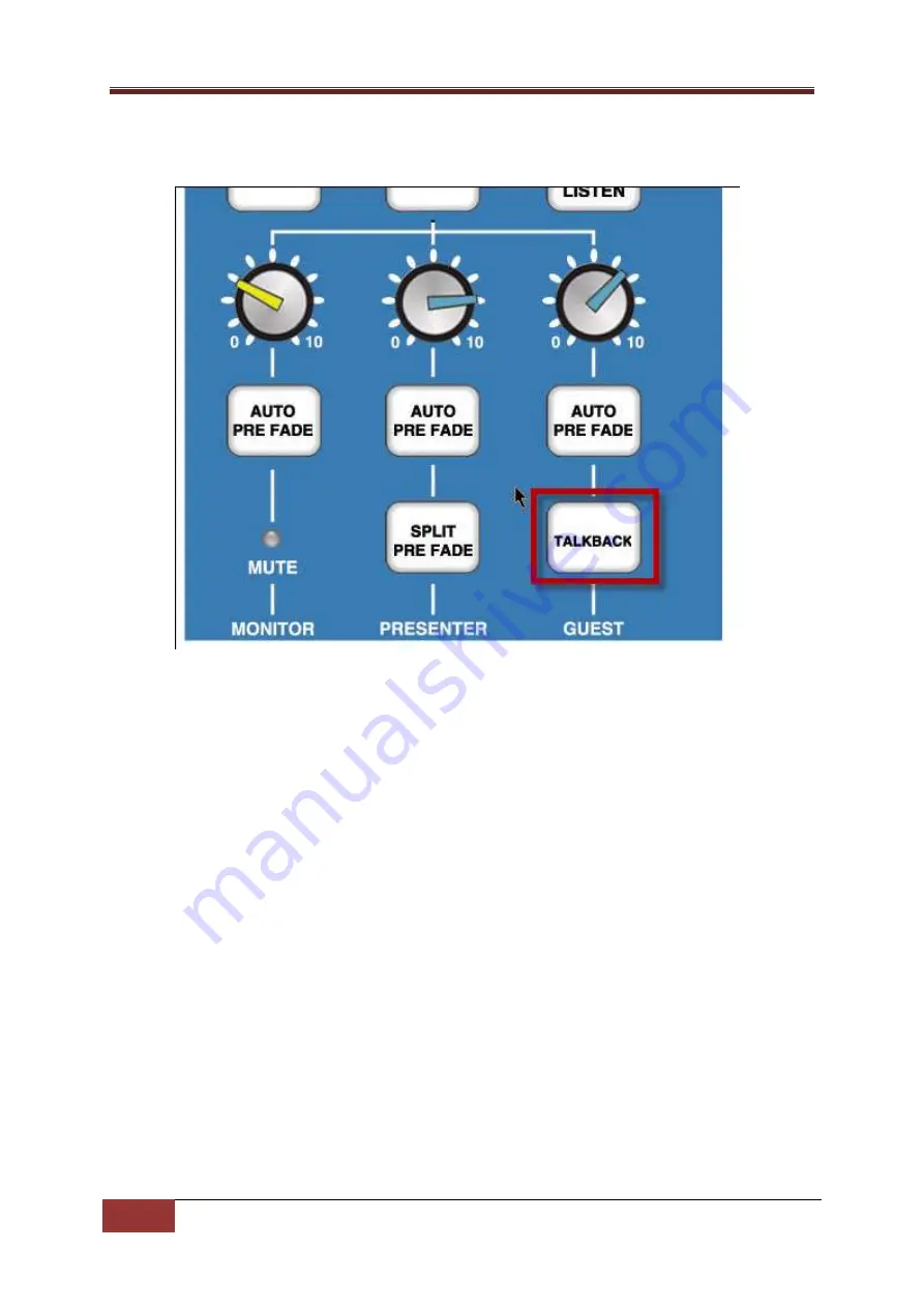
To exit Setup Mode and save your settings, hold down the GUEST TALKBACK button for 2 
seconds. 


The LED Meter display will perform a ‘dual sweep’ to indicate that the SRM has existed 
Setup Mode, the GUEST TALKBACK button can now be released. 
 

Other Channel Configuration – Advanced Settings 

The following section outlines other settings that can be altered using a similar method to above. 

The first thing to consider is that the SRM settings are divided up into ‘pages’ with related settings 
collected onto specific pages. This allows us to use a few buttons to alter a number of settings with 
the same buttons performing different roles depending on what settings ‘page’ is selected. 

The settings ‘page’ that you are working on is displayed on LED Meter display with the position of 
the illuminated portion of the display indicating the ‘page that is selected. So if the lights are lit to 
the number 3 on the LED Meter display then you are working on settings ‘page’ 3. 

So each ‘page’ has a number of settings and also a designated select/indicator button that is used to 
both display the current settings and to step through the available settings. 

Before you can alter any settings, you need to switch the SRM to Setup Mode. 

Switching To Setup Mode 

1.


Ensure all the faders are closed. 

Summary of Contents for SRM

Page 1: ...Operations Manual Last Updated 11 10 2013 P Squared Ltd...

Page 2: ...oftware supplied by the Company the Company does not warrant that the use of the software will be uninterrupted or error free c The Company accepts liability i for death or personal injury to the exte...

Page 3: ...tion 18 Layout Function 18 Rear Panel Layout Function 21 Setting Up The Myriad Intelligent Interface MII 23 What Is MII 23 Start Button Colour Status Key 23 Starting Stopping Playback In Myriad From T...

Page 4: ...hannels 41 Other Channel Configuration Advanced Settings 45 Switching To Setup Mode 45 Selecting The Settings Page You Want To Work With 46 Available Settings 48 Settings Page 1 Input Select Modes 48...

Page 5: ...ralleled levels of interactivity between the two systems and blurring the lines between software and broadcast hardware The SRM is a fixed format nine channel broadcast mixer boasting the following ke...

Page 6: ...6 Layout Dimensions Copyright P Squared Ltd 2013 Layout Dimensions Dimensions Width 482 6mm Height 355 0mm Depth 107mm...

Page 7: ...SRM Operations Manual 7 Layout Dimensions Copyright P Squared Ltd 2013...

Page 8: ...one you can connect an analogue telephone line to the SRM to allow you to make and receive phone calls through the mixing desk standard handset required The AUX stereo input provides a convenient addi...

Page 9: ...layout system This function allows you to select which channels Myriad should record which is very useful when voice tracking or recording telephone calls when live on air etc Button illuminates when...

Page 10: ...to speak into the mic You will be able to hear them through your headphones but crucially you can also see their mic levels on the LED Meter bar graph so you can adjust the channel Trim accordingly O...

Page 11: ...n level for microphones plugged into the channel This is in addition to the Trim control on the channel itself This control should only be adjusted by a competent audio engineer 3 Mic Input This XLR i...

Page 12: ...normally be connected to your Myriad system or other playout system This function allows you to select which channels Myriad should record which is very useful when voice tracking or recording telepho...

Page 13: ...to compatible external devices such as some CD players via the Remote Start Output see rear of channel When in Myriad mode it is used to control the corresponding Cart Player in Myriad and also to di...

Page 14: ...Line Input This RCA phono input allows you to plug in a stereo source that will be used by the channel when in Line mode The source should be domestic level unbalanced as found on most CD players and...

Page 15: ...n illuminates when selected 3 REC Button Record Bus This button allows you to select whether the output from the channel should be mixed into the Record Bus Output which would normally be connected to...

Page 16: ...pecial feature allows you to talk to your caller using Microphone Channel 1 without having to open the Microphone 1 fader So once you have a caller you can use the Pre Fade TB button to listen to them...

Page 17: ...ot need adjusting under normal circumstances 3 Line phone This allows you to connect the SRM to a standard BT analogue phone line You will need an RJ11 male to BT male cable to connect from your BT ph...

Page 18: ...The LED Meter section can be set to display the current volume for any of the following PGM The LED shows the volume for the Program Output Bus main desk output REC The LED shows the volume for the R...

Page 19: ...knob blue top is used to control the volume of the guest headphones Please note that the SRM has an adjustable headphone limiter which prevents the volume of the headphones from going too high Once th...

Page 20: ...thing but also want to keep an ear on what is being broadcast 9 Talkback The Talkback button allows you talk to the Guest Presenter via their headphones If you hold down this button and then talk into...

Page 21: ...PC 4 Program Outputs This is a balanced XLR output that includes a mix of all the channels that have the PGM buttons selected and the faders up This is usually connected to your main transmission syst...

Page 22: ...s jack output provides a signal to an external mic live light whenever a Microphone Channel fader is opened Please note that this output provides a closure between the tip and the Sleeve of the jack a...

Page 23: ...vironment It is assumed that your Myriad system is setup to use four Cart Players and that the Cart Players are connected to Myriad Channels 1 4 on the SRM This means that when you drop a Cart in to C...

Page 24: ...shows the function of pressing the Start button in relation to the corresponding Myriad Cart Player Press Start When Cart Is Cued Paused solid red This will start playback of the Cart Player in Myriad...

Page 25: ...ro computers You will also need to be running Myriad v3 6 1 or higher to use MII 1 Plug a standard USB A to B cable in to the back of the SRM mixer see below and plug the other end into your Myriad pl...

Page 26: ...are and Sound option and finally select Device Manager from the Device Printers section Once Device Manager has loaded expand the Universal Serial Bus Controllers section and you should see USB Serial...

Page 27: ...look to see which COM port the USB Serial Device is assigned to In the above example the USB Serial Port is using COM7 You need to make a note of the COM number it is randomly assigned so that you ca...

Page 28: ...nterface MII Copyright P Squared Ltd 2013 8 Once the Myriad Settings window loads select the Intelligent Int tab should be on the right hand side of the top row of tabs This tab allows you to setup MI...

Page 29: ...e Compatible Mixer option to enable the Connection Details section 2 Select P Squared SRM from the Connected To drop down list You will see the SRM logo displayed to the right of the list Please note...

Page 30: ...when the corresponding faders on the SRM are in the down position This will still allow playback but Myriad will tag them as in preview mode in the playlogs Please note that preview mode caused by SRM...

Page 31: ...t means that it is not working In this scenario the best thing to do is to unplug the SRM wait for 30 seconds and then plug it back in again In most cases this will resolve the situation d If all of t...

Page 32: ...volume on Male RJ11 to BT phone plug male cable to connect from the SRM to the BT phone socket on the wall Tip You should get one of these with your telephone handset Male RJ11 to male RJ11 cable to...

Page 33: ...r handset usually on the side rear or bottom of the handset That is the basic setup complete You can test your connections by listening to the receiver on the phone handset you should get a dial tone...

Page 34: ...all 3 Once the person you have called has answered you can use the handset to talk to them if you wish 4 When you are ready to transfer them to the SRM pull down the TEL Aux fader and press the PREFAD...

Page 35: ...should be able to hear you You can safely replace the handset receiver at this stage but you should leave the handset off the phone cradle if you wish to talk to the caller at the end of broadcast ses...

Page 36: ...Call While You Are On Air For Broadcasting Later The SRM also makes it possible to record a telephone call to your Myriad playout system or other recording equipment when you are on air without the l...

Page 37: ...using for recording but not to the PGM Output bus which is feeding your live output Obviously if you need to use any other channels like guest mic etc then you should set them up the same Important M...

Page 38: ...ord Cart Player again and then press the Line Hold button to hang up the phone call Trouble Shooting Reducing Noise Using The R BAL and C BAL Adjustments The Telephone Interface on the SRM is factory...

Page 39: ...neer SRM Setup Mode The SRM comes pre setup for most common applications but there are a number of additional programming options that can be adjusted to meet your individual needs The SRM can be setu...

Page 40: ...n PPM VU Modes The LED Meters can be switched to display in PPM or VU modes with PPM set as the default In PPM mode the display shows an average volume of a short time period so the display is more co...

Page 41: ...will be no effect as the internal wiring is such that the phantom power circuit is not completed There is a chance with damaged microphones or very old or sub standard microphones that plugging into a...

Page 42: ...pyright P Squared Ltd 2013 A single meter sweep indicates entry into Setup Mode and the buttons can be released 3 Once the sweep on the LED Meter has completed the LED Meter should be indicating the n...

Page 43: ...SRM are divided into separate pages with different settings on each page The phantom power settings are on page one so the LED Meter must be displaying 1 before you continue If another number is indic...

Page 44: ...nly Phantom power not applicable To select the mode you require press the Mic Line button at the top of the channel to toggle between the available modes The selected mode will be represented by the b...

Page 45: ...specific pages This allows us to use a few buttons to alter a number of settings with the same buttons performing different roles depending on what settings page is selected The settings page that yo...

Page 46: ...try into setup mode and the buttons can be released Selecting The Settings Page You Want To Work With As outlined above the settings are divided into separate pages with common settings clustered on a...

Page 47: ...SRM Operations Manual 47 SRM Setup Mode Copyright P Squared Ltd 2013 To step through the available setting pages press the GUEST TALKBACK button Each press will advance the settings page number by one...

Page 48: ...rrent mode is displayed by the button flashing the appropriate amount of times pausing briefly and then repeating the flash pattern So for example the Mic Line button on the SRM is used to select the...

Page 49: ...s current mode Mode 1 TEL Aux1 Aux2 available for selection Mode 2 TEL Aux1 available for selection default Mode 3 TEL Aux2 available for selection Mode 4 TEL only Mode 5 Aux1 Aux2 available for selec...

Page 50: ...ching remote start when line hold active ringing indicated on remote stop available on channel 9 TEL only Mode 3 Momentary start stop with repeat start enabled Mode 4 Momentary start stop with repeat...

Page 51: ...EL Mode 2 Aux Rear Mode 3 Aux Front Mode 3 Saving Settings And Existing Setup Mode To exit Setup Mode and save your settings hold down the GUEST TALKBACK button for 2 seconds The LED Meter display wil...

Page 52: ...eadphone Output Load Jack 16 recommended 250 Input Output Gain Range Mic Inputs Preset pot 24dB to 67dB ref 50dBu TRIM pot 15dB Stereo Line Input 10dB ref 0dBu at PGM output TRIM pot 15dB Frequency Re...

Page 53: ...hone XLR 3 pin female 1 x Stereo line pair phono sockets 1 x Remote Output 6 35mmm Stereo Jack socket Dual Stereo Channels 4 channels each comprising of 2 x Stereo line pair phono sockets 1 x Remote O...

Page 54: ...o Jack socket Monitor Output 1 x 3 5mm Stereo Jack socket Aux Input Mains Input Filtered IEC continuously rated 85 264VAC 47 63Hz 45w nominal 50w peak Fuse Rating Anti surge fuse 2A 20 x 5mm Physical...

Page 55: ...ine Inputs RCA Phono Line Inputs 1 6 Myriad Inputs 5 8 Signal Pin Signal Tip Ground Sleeve Remote Outputs 1 4 Stereo Jack Channels 1 9 Signal Pin Start Tip Stop Ring Ground Sleeve Line Handset These c...

Page 56: ...Control 1 4 Stereo Jack Monitor I O Panel Signal Pin Normally Open Tip Normally Closed Ring Common Ground Sleeve USB Serial Use a standard USB A to B lead to connect the SRM to your Myriad PC Only us...

Page 57: ...SRM Operations Manual 57 Connectors Pin Outs Copyright P Squared Ltd 2013 Connector diagrams provided courtesy of Sonifex Ltd...

Page 58: ...58 Notes Copyright P Squared Ltd 2013 Notes...

Page 59: ...2013 P Squared Contact Details P Squared Ltd 1 2 Maritime House Livingstone Road Hessle East Riding Of Yorkshire UK HU130EG Telephone 44 0 1482 350700 Fax 44 0 1482 350701 Email sales sales psquared n...

Reviews: