SECTION 5 - BASIC HYDRAULIC INFORMATION & HYDRAULIC SCHEMATICS
3121262
– JLG Lift –
5-5
Assembly And Torque Specifications
Prior to selecting the appropriate torque from the tables
within this section, it is necessary to properly identify the con-
nector being installed. Refer to the Figures and Tables in this
section.
GENERAL TUBE TYPE FITTING ASSEMBLY
INSTRUCTIONS
1.
Take precautions to ensure that fittings and mating
components are not damaged during storage, handling
or assembly. Nicks and scratches in sealing surfaces can
create a path for leaks which could lead to component
contamination and/or failure.
2.
When making a connection to tubing, compression or
flare, inspect the tube in the area of the fitting attach-
ment to ensure that the tube has not been damaged.
3.
The assembly process is one of the leading causes for
contamination in air and hydraulic systems. Contamina-
tion can prevent proper tightening of fittings and adapt-
ers from occurring.
a.
Avoid using dirty or oily rags when handling fittings.
b.
If fittings are disassembled, they should be cleaned
and inspected for damage. Replace fittings as nec-
essary before re-installing.
c.
Sealing compounds should be applied where speci-
fied; however, care should be taken not to introduce
sealant into the system.
d.
Avoid applying sealant to the area of the threads
where the sealant will be forced into the system.
This is generally the first two threads of a fitting.
e.
Sealant should only be applied to the male threads.
f.
Straight thread fittings do not require sealants. O-
rings or washers are provided for sealing.
g.
When replacing or installing an O-ring, care is to be
taken while transferring the O-ring over the threads
as it may become nicked or torn. When replacing an
O-ring on a fitting, the use of a thread protector is
recommended.
h.
When installing fittings with O-rings, lubrication
shall be used to prevent scuffing or tearing of the O-
ring. See O-ring Installation (Replacement) in this
section.
4.
Take care to identify the material of parts to apply the
correct torque values.
a.
Verify the material designation in the table head-
ings.
b.
If specifications are given only for steel fittings and
components, the values for alternate materials shall
be as follows: Aluminum and Brass- reduce steel val-
ues by 35%; Stainless Steel- Use the upper limit for
steel.
5.
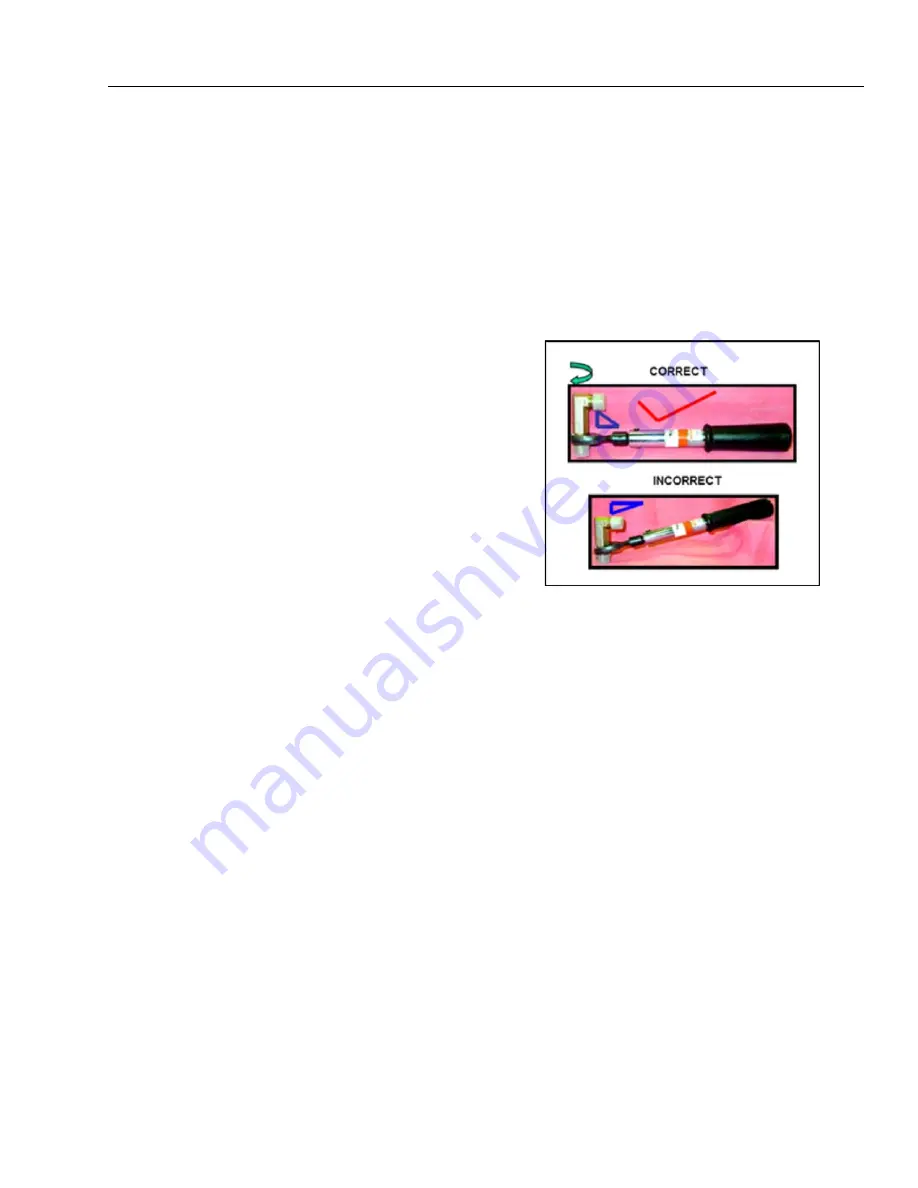
To achieve the specified torque, the torque wrench is to
be held perpendicular to the axis of rotation.
6.
Refer to the appropriate section in this manual for more
specific instructions and procedures for each type of fit-
ting connection
Figure 5-11. Torque Wrench Angle
Summary of Contents for JLG 1500SJ
Page 1: ...Service and Maintenance Manual Model 1500SJ P N 3121262 March 7 2016...
Page 2: ......
Page 24: ...xx JLG Lift 3121262 LIST OF TABLES TABLE NO TITLE PAGE NO This page left blank intentionally...
Page 40: ...SECTION 1 SPECIFICATIONS 1 16 JLG Lift 3121262 NOTES...
Page 62: ...SECTION 3 CHASSIS TURNTABLE 3 12 JLG Lift 3121262 Figure 3 11 Axle Loctite Application...
Page 186: ...SECTION 3 CHASSIS TURNTABLE 3 136 JLG Lift 3121262 Figure 3 72 EMR2 Fault Codes Sheet 1 of 5...
Page 187: ...SECTION 3 CHASSIS TURNTABLE 3121262 JLG Lift 3 137 Figure 3 73 EMR2 Fault Codes Sheet 2 of 5...
Page 188: ...SECTION 3 CHASSIS TURNTABLE 3 138 JLG Lift 3121262 Figure 3 74 EMR2 Fault Codes Sheet 3 of 5...
Page 189: ...SECTION 3 CHASSIS TURNTABLE 3121262 JLG Lift 3 139 Figure 3 75 EMR2 Fault Codes Sheet 4 of 5...
Page 190: ...SECTION 3 CHASSIS TURNTABLE 3 140 JLG Lift 3121262 Figure 3 76 EMR2 Fault Codes Sheet 5 of 5...
Page 202: ...SECTION 3 CHASSIS TURNTABLE 3 152 JLG Lift 3121262...
Page 204: ...SECTION 3 CHASSIS TURNTABLE 3 154 JLG Lift 3121262...
Page 206: ...SECTION 3 CHASSIS TURNTABLE 3 156 JLG Lift 3121262...
Page 216: ...SECTION 3 CHASSIS TURNTABLE 3 166 JLG Lift 3121262...
Page 218: ...SECTION 3 CHASSIS TURNTABLE 3 168 JLG Lift 3121262...
Page 220: ...SECTION 3 CHASSIS TURNTABLE 3 170 JLG Lift 3121262...
Page 222: ...SECTION 3 CHASSIS TURNTABLE 3 172 JLG Lift 3121262...
Page 224: ...SECTION 3 CHASSIS TURNTABLE 3 174 JLG Lift 3121262...
Page 240: ...SECTION 3 CHASSIS TURNTABLE 3 190 JLG Lift 3121262...
Page 244: ...SECTION 3 CHASSIS TURNTABLE 3 194 JLG Lift 3121262...
Page 273: ...SECTION 4 BOOM PLATFORM 3121262 JLG Lift 4 25 Figure 4 6 Boom Assembly Sheet 7 of 7...
Page 305: ...SECTION 4 BOOM PLATFORM 3121262 JLG Lift 4 57 Figure 4 14 Jib Assembly Sheet 2 of 3...
Page 318: ...SECTION 4 BOOM PLATFORM 4 70 JLG Lift 3121262 Figure 4 18 Powertrack Hosing Sheet 2 of 3...
Page 319: ...SECTION 4 BOOM PLATFORM 3121262 JLG Lift 4 71 Figure 4 19 Powertrack Hosing Sheet 3 of 3...
Page 332: ...SECTION 4 BOOM PLATFORM 4 84 JLG Lift 3121262 Figure 4 22 Outer Mid Boom Extend Retract Cables...
Page 333: ...SECTION 4 BOOM PLATFORM 3121262 JLG Lift 4 85 Figure 4 23 Fly Boom Extend Retract Cables...
Page 350: ...SECTION 4 BOOM PLATFORM 4 102 JLG Lift 3121262 Figure 4 29 Rotator Counterbalance Valve...
Page 516: ...SECTION 5 BASIC HYDRAULIC INFORMATION HYDRAULIC SCHEMATICS 5 162 JLG Lift 3121262 NOTES...
Page 536: ...SECTION 6 JLG CONTROL SYSTEM 6 20 JLG Lift 3121262 Figure 6 2 Control System Block Diagram...
Page 545: ...SECTION 6 JLG CONTROL SYSTEM 3121262 JLG Lift 6 29 Figure 6 10 Control Module Location...
Page 704: ...SECTION 7 BASIC ELECTRICAL INFORMATION ELECTRICAL SCHEMATICS 7 60 JLG Lift 3121262 NOTES...
Page 705: ......


