background image

SECTION 7 - BASIC ELECTRICAL INFORMATION & ELECTRICAL SCHEMATICS

7-112

– JLG Lift –

3121659

Figure 7-116.  Electrical Schematic - Sheet 14 of 17

Summary of Contents for JLG 450AJ

Page 1: ...Service and Maintenance Manual Model 450AJ S N 0300199221 to Present P N 3121659 October 9 2015...

Page 2: ......

Page 3: ...raulic systems oper ate at extremely high potentially dangerous pressures Every effort should be made to relieve any system pressure prior to disconnecting or removing any portion of the system Do not...

Page 4: ...INTRODUCTION A 2 JLG Lift 3121659 REVISON LOG Original Issue March 13 2015 Revised October 9 2015...

Page 5: ...n 2 1 Preventive Maintenance 2 1 2 2 Service and Guidelines 2 2 General 2 2 Safety and Workmanship 2 2 Cleanliness 2 2 Components Removal and Installation 2 2 Component Disassembly and Reassembly 2 3...

Page 6: ...e Motor 3 19 Description 3 19 Shaft Seal Replacement 3 20 Loop Flushing Valve 3 20 Troubleshooting 3 21 Disassembly 3 22 Inspection 3 26 Assembly 3 28 Initial Start Up Procedures 3 32 3 5 Drive Brake...

Page 7: ...n Relief 5 33 Platform Level Up Relief 5 33 Platform Level Down Relief 5 34 5 3 DRIVE PUMP PRE FILL PROCEDURE 5 34 SECTION 6 JLG CONTROL SYSTEM 6 1 JLG Control System Analyzer Kit Instructions 6 1 Int...

Page 8: ...Applying Silicone Dielectric Compound to Electrical Connections 7 3 Installation of Dielectric Grease 7 4 Deutsch HD DT DTM DRC Series 7 4 AMP Seal 7 4 AMP Mate N Lok 7 5 DIN Connectors 7 5 Exclusions...

Page 9: ...and 4WD Sheet 2 of 2 3 5 3 4 Drive Hub 4WD Front Only Sheet 1 of 2 3 6 3 5 Drive Hub 4WD Front Only Sheet 2of 2 3 7 3 6 Cluster Gear Punch Marks 3 15 3 7 Drive Motor Cross Section 3 19 3 8 Removing Sh...

Page 10: ...0 of 30 5 12 5 11 Hydraulics Installation Sheet 11 of 30 5 13 5 12 Hydraulics Installation Sheet 12 of 30 5 14 5 13 Hydraulics Installation Sheet 13 of 30 5 15 5 14 Hydraulics Installation Sheet 14 of...

Page 11: ...nector Assembly Figure 2 7 8 7 10 Connector Assembly Figure 3 7 8 7 11 Connector Assembly Figure 4 7 8 7 12 Connector Disassembly 7 9 7 13 Connector Installation 7 10 7 14 DT DTP Contact Installation...

Page 12: ...ss Sheet 1 of 3 7 54 7 60 Chassis Solenoid Harness Sheet 2 of 3 7 55 7 61 Chassis Solenoid Harness Sheet 3 of 3 7 56 7 62 Main Valve Harness Sheet 1 of 8 7 57 7 63 Main Valve Harness Sheet 2 of 8 7 58...

Page 13: ...of 5 7 94 7 100 Chassis Head and Tail Lights Harness Sheet 3 of 5 7 95 7 101 Chassis Head and Tail Lights Harness Sheet 4 of 5 7 96 7 102 Chassis Head and Tail Lights Harness Sheet 5 of 5 7 97 7 103...

Page 14: ...1 Inspection and Maintenance 2 2 2 2 Cylinder Drift 2 5 2 3 Inspection and Preventive Maintenance Schedule 2 6 3 1 Wheel Torque Chart 3 1 3 2 Excessive Noise and or Vibration 3 21 3 3 System Operatin...

Page 15: ...ensional Data TurningRadius Inside 6 9 2 06m TurningRadius Outside 15 8 4 78m MachineHeight stowed 89 3 2269mmm MachineLength stowed 258 9 6576mm UpandOverPlatformHeight 24 7 3m HorizontalReach 25 7 6...

Page 16: ...oke 4 3in 110mm TotalDisplacement 178cu in 2925cm3 FiringOrder 1 3 4 2 Output 49hp 36 5kW OilCapacity 2 4gal 8 9L CoolantCapacity System 3 2gal 12 1L AverageFuelConsumption 1 2gph 4 1Lph Min LowEngine...

Page 17: ...59 F PourPoint 20 C 4 F FlashPoint 275 C 527 F FirePoint 325 C 617 F AutoignitionTemperature 450 C 842 F Viscosity at0 C 32 F 360cSt at20 C 68 F 102cSt at40 C 104 F 46cSt at100 C 212 F 10cSt Viscosity...

Page 18: ...n Comments Apply grease and rotate in 90 degree inter vals until bearing is completely lubricated 2 Swing Bearing Worm Gear Teeth Lube Point s Grease Fitting Capacity A R Lube Lubriplate 930 AAA Inter...

Page 19: ...level in reservoir 4 Hydraulic Return Filter Lube Point s Replaceable Element Interval Change after first 50 hours and every 6 months or 300 hours thereafter 5 Hydraulic Tank Breather Interval Change...

Page 20: ...Spin on Element Capacity 10 Quarts 9 5 L w Filter Lube EO Interval Check level daily change every 500 hours or six months whichever comes first Adjust final oil level by mark on dipstick 9 Oil Change...

Page 21: ...val 3 Months or 150 hours of operation Comments Check level daily Change in accordance with engine manual 11 Fuel Filter Water Separator Deutz 2 3 L3 Lube Point s Replaceable Element Interval Every ye...

Page 22: ...ine GM Lube Point s Replaceable Element Interval Every 6 months or 300 hours of operation 15 Fuel Filter Propane GM Engine Interval 3 Months or 150 hours of operation Comments Replace filter 16 Charge...

Page 23: ...nths or 300 hours of operation or as indicated by the condition indicator Comments Check Dust Valve daily 18 Engine Coolant Lube Point s Fill Cap Capacity Deutz 2 9L 2 9 gal 11 3L Capacity GM 3 0L 2 4...

Page 24: ...SECTION 1 SPECIFICATIONS 1 10 JLG Lift 3121659 Figure 1 1 Maintenance and Lubrication Diagram Deutz 2 3 Engine...

Page 25: ...SECTION 1 SPECIFICATIONS 3121659 JLG Lift 1 11 Figure 1 2 Maintenance and Lubrication Diagram GM Engine...

Page 26: ...SECTION 1 SPECIFICATIONS 1 12 JLG Lift 3121659 Figure 1 3 Maintenance and Lubrication Diagram Deutz 2 9 Engine...

Page 27: ...SECTION 1 SPECIFICATIONS 3121659 JLG Lift 1 13 Figure 1 4 Torque Chart Sheet 1 of 5 SAE Fasteners...

Page 28: ...SECTION 1 SPECIFICATIONS 1 14 JLG Lift 3121659 Figure 1 5 Torque Chart Sheet 2 of 5 SAE Fasteners...

Page 29: ...SECTION 1 SPECIFICATIONS 3121659 JLG Lift 1 15 Figure 1 6 Torque Chart Sheet 3 of 5 SAE Fasteners...

Page 30: ...SECTION 1 SPECIFICATIONS 1 16 JLG Lift 3121659 Figure 1 7 Torque Chart Sheet 4 of 5 METRIC Fasteners...

Page 31: ...SECTION 1 SPECIFICATIONS 3121659 JLG Lift 1 17 Figure 1 8 Torque Chart Sheet 5 of 5 METRIC Fasteners...

Page 32: ...SECTION 1 SPECIFICATIONS 1 18 JLG Lift 3121659 NOTES...

Page 33: ...r 3 months or 150 hours whichever comes first out of service for a period of more than 3 months or when purchased used The frequency of this inspection must be increased as environ ment severity and f...

Page 34: ...their containers until they are ready to be used Components Removal and Installation 1 Use adjustable lifting devices whenever possible if mechanical assistance is required All slings chains cables et...

Page 35: ...INTENDED TO BE REINSTALLED AFTER REMOVAL 1 Always use new replacement hardware when installing locking fasteners Use bolts of proper length A bolt which is too long will bottom before the head is tig...

Page 36: ...hanging Hydraulic Oil 1 Filter elements must be changed after the first 50 hours of operation and every 300 hours unless specified oth erwise thereafter If it is necessary to change the oil use only t...

Page 37: ...e cleaned with a solvent to remove all grease and oil filament wound bearing are a dry joint and should not be lubricated unless otherwise instructed i e sheave pins c Pins should be inspected to ensu...

Page 38: ...2 1 2 WearPads 1 2 1 2 CoversorShields 1 2 1 2 Extend RetractChainorCableSystems 1 2 3 1 2 3 BoomAssembly 14 PlatformAssembly Platform 1 2 Railing 1 1 2 Gate 5 1 1 5 Floor 1 1 2 Rotator 9 5 15 Lanyar...

Page 39: ...Pumps 1 9 1 2 9 HydraulicCylinders 1 9 7 2 1 2 9 1 2 9 CylinderAttachmentPinsandPinRetainers 1 9 1 2 1 2 HydraulicHoses Lines andFittings 1 9 12 1 2 9 12 1 2 9 12 HydraulicReservoir Cap andBreather 1...

Page 40: ...ation 2 Visualinspectionfordamage cracks distortionorexcessivewear 3 Checkforproperadjustment 4 Checkforcrackedorbrokenwelds 5 OperatesProperly 6 Returnstoneutralor off positionwhenreleased 7 Cleanand...

Page 41: ...SECTION 2 GENERAL 3121659 JLG Lift 2 9 Figure 2 1 Engine Operating Temperature Specifications Deutz 2 9 1001159163 A...

Page 42: ...on Viscosity at 40 C cSt Typical Viscosity Index Mineral Oils Vegetable Oils Synthetic Synthetic Polyol Esters Readily Biodegradable Virtually Non toxic Fire Resistant Mobilfluid424 55 145 X MobilDTE1...

Page 43: ...SECTION 2 GENERAL 3121659 JLG Lift 2 11 Figure 2 3 GM Engine and Hydraulic Oil Operating Temperature Specifications...

Page 44: ...SECTION 2 GENERAL 2 12 JLG Lift 3121659 Figure 2 4 Deutz 2011 Engine and Hydraulic Oil Operating Temperature Specifications...

Page 45: ...Size changes such as rim width center piece location larger or smaller diameter etc without written factory recommendations may result in an unsafe condition regarding stability Wheel Installation It...

Page 46: ...air tight You can tell if your unit has a leak if pressure gauge test reading starts to fall once you have pressurized the unit Leaks usually occur at the main seal or wherever O rings or gaskets are...

Page 47: ...16 Remove O ring 5 from counterbore in hub 1G Dis card O ring 17 Main disassembly for B drives is complete Hub Spindle Disassembly NOTE Start with large end of hub facing up and large end of spin dle...

Page 48: ...SECTION 3 CHASSIS TURNTABLE 3 4 JLG Lift 3121659 Figure 3 2 Drive Hub and Brake Assembly 2WD and 4WD Sheet 1 of 2...

Page 49: ...utSpacer 113 Capscrew 1H ThrustWasher 6D DisconnectRod 17 BrakeAssembly 114 Lockwasher 1I RetainingRing 6E DisengageCap 27 O Ring 115 O Ring 1N WheelStud 6F Bolt 28 ThreadedRod 116 Back upRing 2 Inter...

Page 50: ...SECTION 3 CHASSIS TURNTABLE 3 6 JLG Lift 3121659 Figure 3 4 Drive Hub 4WD Front Only Sheet 1 of 2...

Page 51: ...g 7D ThrustSpacer 1D BearingCup 3D ThrustWasher 6D DisconnectRod 8 Gear Sun 1E BearingCup 3E PlanetShaft 6E DisengageCap 11 ThrustWasher 1F BearingCone 3F PlanetGear 6F Bolt 12 Bolt 1G Housing RingGea...

Page 52: ...SHAFT IS REMOVED 2 Using a punch and hammer drive planet shaft 3E out of planet shaft hole in carrier housing 3A 3 When you remove planet shaft 3E from carrier housing one thrust washer 38 one cluster...

Page 53: ...g thrust washer place cluster gear 3F large end toward roll pin hole in carrier housing on planet shaft 3E 7 Following cluster gear place one more thrust washer 3B onto planet shaft 3E through opposit...

Page 54: ...against flange of cover cap 3 Insert disconnect rod 6E into cover cap 6B 4 Set cover 6A on table exterior side up Place cover cap 6B on cover 6A Align pipe plug hole in cover cap over pipe plug hole i...

Page 55: ...scon nect cap 6D and tighten bolts 9 Using a torque wrench apply 36 to 49 in lb 4 to 5 Nm of torque to both bolts 6C 10 Apply a light coat of Never Seize to pipe plug 6H and tighten it in pipe plug ho...

Page 56: ...Make sure cup sits square with counterbore before press ing 4 Turn hub 1G over to small end Press bearing cup 1E into counterbore in deep end of hub 1G 5 Set hub 1G on large end Place bearing cone 1D...

Page 57: ...ndle sub assembly is complete Main Assembly SHARP EDGES CAN CUT AND CAUSE SERIOUS INJURY BEWARE OF SHARP EDGES IN COUNTERBORE WHEN REMOVING O RING 1 Grease O ring 5 and place it into counterbore in hu...

Page 58: ...put shaft 7A 5 Place spring 7C on smooth end of input shaft 7A 6 Place other spacer 7D on smooth end of input shaft 7A UNCONTROLLED OBJECTS CAN CAUSE EYE DAMAGE OR SERIOUS INJURY ALWAYS WEAR EYE PROTE...

Page 59: ...assembly 3 and ring gear 4 together into mesh with internal gear 2 aligning X marked shoulder bolt hole in ring gear 4 over one of the shoul der bolt holes in hub Mark location of shoulder bolt holes...

Page 60: ...y be stretched or pinched together to make it fit counterbore 16 Place cover sub assembly 6 on ring gear 4 Align pipe plug holes before disassembly 17 Place four flat washers 16 on top of bolt holes i...

Page 61: ...side Insert coupling 14 into end of spindle 1A 23 Roll test unit in clockwise and counterclockwise direc tions Perform same number of turns in each direction as the ratio of the unit The ratio is the...

Page 62: ...m mild steel All dimensions are in inches NOTE Tools may be carburized and hardened to improve tool life If this is done tools must be ground on all surfaces labeled with a G on the tool diagram 1 T 1...

Page 63: ...port Coupling remains in position 5 Disconnect hydraulic power supply and reconnect line to brake release port 3 4 DRIVE MOTOR Description Drive motors are low to medium power two position axial pis t...

Page 64: ...stall snap ring 1 5 Remove installation sleeve Loop Flushing Valve REMOVAL 1 Removeplug 1 and 2 with11 16 internalhexwrench Figure 3 9 Loop Flushing Spool 2 Use 1 4 in hex wrench to remove plug 3 3 Re...

Page 65: ...iption Action Checkoillevelinreservoirandoil supplytopump Insufficientamountofhydraulicfluidwillnotmeetsystemcooling demands Fillreservoirtoproperlevel Inspectheatexchanger ifequipped Ifheatexchangerf...

Page 66: ...pped and remove speed sensor Units without speed sensor have an O ring plug 15 installed in that location remove it with a 1 4 inch internal hex wrench 10 Using a 1 4 internal hex wrench remove contro...

Page 67: ...late The last two digits of the part number are stamped on its surface 16 Remove and discard O rings 27 28 17 Remove rear shaft bearing 29 from endcap with a bear ing puller DO NOT DRIVE BEARING PAST...

Page 68: ...damaging shaft during seal removal Install a large sheet metal screw in chuck of a slide hammer Drive screw into seal surface Use slide hammer to pull seal 21 Remove inner snap ring 35 and shaft bear...

Page 69: ...K OF PERSONAL INJURY COMPRESSING BLOCK SPRING REQUIRES FORCE OF ABOUT 80 TO 90 LBF 350 TO 400 N USE A PRESS SUFFICIENT TO MAIN TAIN THIS FORCE WITH REASONABLE EFFORT ENSURE SPRING IS SECURE BEFORE ATT...

Page 70: ...ximum axial end play are shown in table 3 6 BALL GUIDE AND SLIPPER RETAINER Inspect ball guide and slipper retainer for damage discolor ation or excessive wear A discolored ball guide or slipper retai...

Page 71: ...bearings for damage or excessive wear Replace journal bearings if scratched warped or excessively worn Polymer wear layer must be smooth and intact SHAFT BEARINGS Inspect bearings for excessive wear o...

Page 72: ...BLOCK SPRING REQUIRES ABOUT 80 TO 90 LBF 350 TO 400 N OF FORCE USE A PRESS SUFFICIENT TO MAINTAIN THIS FORCE WITH REASONABLE EFFORT ENSURE SPRING IS SECURE BEFORE ATTEMPTING TO INSTALL SPIRAL RETAINI...

Page 73: ...install them in original location and orientation Lubricate journal bearings 7 Install swashplate 14 in housing Tilt swashplate and guide servo lever ball into its socket in servo piston rod Ensure sw...

Page 74: ...ntil bearing surface is 0 08 0 01 in 2 0 25 mm above endcap surface 13 Install timing pin 23 into bore in endcap Install pin with groove facing toward or away from shaft Press pin until end protrudes...

Page 75: ...alling shaft seal ensure shaft turns smoothly with less than 120 in lb 13 5 Nm of force If shaft does not turn smoothly within specified force disassemble and check unit 18 Cover shaft splines with an...

Page 76: ...hydraulic fluid Pour filtered oil directly into upper most case drain port 4 Install case drain lines into upper most case drain ports to ensure pump and motor stay filled with oil 5 Install a 0 to 50...

Page 77: ...ompression springs 22 23 for damage or fatigue 5 Check the ball bearing 10 for axial float or wear 6 Examine O ring seals 15 17 and backing rings 16 18 for damage Assembly 1 Lightly lubricate the rota...

Page 78: ...Housing 3 InnerFrictionPlate 4 PressurePlate 5 Gasket NotShown 6 OuterPlate 7 Gasket 8 Cylinder 9 Piston 10 BallBearing 11 RetainingRing 12 RotaryShaftSeal 13 SocketHeadCapscrew 14 Washer 15 O ring 16...

Page 79: ...l link and turntable f Remove hardware securing lower boom pivot pin Using a suitable brass drift and hammer remove pin from the turntable g Using all applicable safety precautions carefully lift boom...

Page 80: ...SECTION 4 BOOM PLATFORM 4 2 JLG Lift 3121659 Figure 4 1 Boom Assembly...

Page 81: ...SECTION 4 BOOM PLATFORM 3121659 JLG Lift 4 3 Figure 4 2 Main Boom Assembly Sheet 1 of 2...

Page 82: ...SECTION 4 BOOM PLATFORM 4 4 JLG Lift 3121659 Figure 4 3 Main Boom Assembly Sheet 2 of 2...

Page 83: ...SECTION 4 BOOM PLATFORM 3121659 JLG Lift 4 5 Figure 4 4 Upper Boom Assembly...

Page 84: ...SECTION 4 BOOM PLATFORM 4 6 JLG Lift 3121659 Figure 4 5 Jib Assembly...

Page 85: ...ch power track to aft end of fly boom section Secure power track with attaching hardware 6 Using suitable lifting equipment slide fly boom section out to gain access to telescope cylinder attach pin h...

Page 86: ...e frequent inspections and maintenance when used in these types of environ ments 2 JLG recommends that you follow all guidelines for ser vicing your equipment in accordance with the instruc tions outl...

Page 87: ...e bottom wear pads on the fly boom and shim as required to obtain the total base boom dimension within 0 1 2 mm of the corresponding dimension from Step 1 5 Slide the fly boom into the base boom leavi...

Page 88: ...SECTION 4 BOOM PLATFORM 4 10 JLG Lift 3121659 Figure 4 8 Cables and Clamps Installation Sheet 1 of 8...

Page 89: ...SECTION 4 BOOM PLATFORM 3121659 JLG Lift 4 11 Figure 4 9 Cables and Clamps Installation Sheet 2 of 8...

Page 90: ...SECTION 4 BOOM PLATFORM 4 12 JLG Lift 3121659 Figure 4 10 Cables and Clamps Installation Sheet 3 of 8...

Page 91: ...SECTION 4 BOOM PLATFORM 3121659 JLG Lift 4 13 Figure 4 11 Cables and Clamps Installation Sheet 4 of 8...

Page 92: ...SECTION 4 BOOM PLATFORM 4 14 JLG Lift 3121659 Figure 4 12 Cables and Clamps Installation Sheet 5 of 8...

Page 93: ...SECTION 4 BOOM PLATFORM 3121659 JLG Lift 4 15 Figure 4 13 Cables and Clamps Installation Sheet 6 of 8...

Page 94: ...SECTION 4 BOOM PLATFORM 4 16 JLG Lift 3121659 Figure 4 14 Cables and Clamps Installation Sheet 7 of 8...

Page 95: ...SECTION 4 BOOM PLATFORM 3121659 JLG Lift 4 17 Figure 4 15 Cables and Clamps Installation Sheet 8 of 8...

Page 96: ...et screws or pins Required Tools Basic tools required for assembly and disassembly of the actu ator and their intended functions are as follows 1 Flashlight helps examine timing marks component failur...

Page 97: ...Shaft 3 PistonSleeve 4 EndCap 5 ExclusionSeal 8 Bolt 9 CapSeal 10 CapRing 11 RodSeal 12 PistonSeal 13 BearingPacking 14 CapBearing 15 ShaftBearing 16 ThrustWasher 17 CounterbalanceValve 53 LockPin 54...

Page 98: ...in to a depth of approximately 3 16 4 76mm 3 Remove lock pins using an Easy Out 2 shown If pin will not come out with Easy Out use 5 16 drill bit to a depth of 1 2 12 7mm and drill out entire pin 4 In...

Page 99: ...aft 2 This simplifies timing during assembly 9 Remove shaft 2 It may be necessary to strike threaded end of shaft with a rubber mallet 10 Mark housing 1 ring gear in relation to piston O D gear before...

Page 100: ...3 Remove O ring 9 and backup ring 10 from end cap 4 and set aside 14 Remove wear guides 14 from end cap 4 and shaft 2 15 To remove main pressure seals 13 it is easiest to cut them using a sharp razor...

Page 101: ...arts in a solvent tank and dry with compressed air before inspecting Inspect seal grooves bearing grooves thrust surfaces rod surface housing bore and gear teeth for surface finish abnormalities 2 Ins...

Page 102: ...ondition Measure thickness not less than 0 123 3 12 mm Assembly 1 Gather all components and tools to one location 2 Install thrust washer 16 on shaft 2 and end cap 4 3 Install exclusion seal 5 in groo...

Page 103: ...6 Install inner T seal 11 in piston 3 using a circular motion 7 Install outer T seal 12 by stretching it around groove in a circular motion Each T seal has 2 back up rings see drawing for orientation...

Page 104: ...rubber mallet tap piston into housing to point where gear teeth meet 13 Look from opposite end of housing 1 to see if timing marks line up When they do tap piston 3 in until gear teeth mesh together T...

Page 105: ...t until gear teeth engage 16 Install 2 bolts in threaded holes in flange Using a bar rotate shaft clockwise until wear guides are seated inside housing bore 17 Coat threads on end of shaft with anti s...

Page 106: ...stays in place on end cap as it is threaded in hous ing 1 20 Tighten end cap 4 and align holes for lock pins 21 Place lock pins 53 provided in Helac seal kit in holes with dimple side up Using a punch...

Page 107: ...s including old Loctite 2 Make sure new valve has O rings in counterbores of valve to seal it to actuator housing 3 Bolts that come with valve are grade 8 bolts Install new bolts with a new valve Appl...

Page 108: ...1659 A B C D E Torqueto50ft lb 68Nm Loctite 242 Torqueto480ft lb 650Nm Checktorqueevery150hoursofoperation Torqueto85ft lb 115Nm Figure 4 18 Platform Support Torque Values NOTE Retorque all bolts on r...

Page 109: ...for example only Actual hose and cable arrangements are different 1 Clamp bar and poly roller tightly so they do not spin when removing screw With a small ratchet and a T 20 torx bit remove 8 32 x 0 5...

Page 110: ...matic die grinder with a ball double cut bur attachment 4 insert tool into rolled over end of rivet Grind out middle of rivet until rolled over part of rivet falls off Repeat for all rivets to be remo...

Page 111: ...SECTION 4 BOOM PLATFORM 3121659 JLG Lift 4 33 6 Insert flat head screwdriver between links Twist and pull links apart 7 Remove link from other section of powertrack using screwdriver...

Page 112: ...e cut out end of new link into half shear female end of track section 2 Spread half shear female end of new link and slide cut out end of track section into it Use a screwdriver if nec essary 3 After...

Page 113: ...posi tioned in curve of powertrack Round half shears will rotate into cut outs 5 Parts shown below connect new link to powertrack 6 Push pin through center hole then slide washer on pin 7 Install sna...

Page 114: ...ap rings are seated in pin groove and closed properly 1 Install new 8 32 x 0 500 self threading torx head screw in end of new aluminum round bar Torque to 18 20 in lb 2 2 25 Nm 2 Pull up on other end...

Page 115: ...20 in lb 2 2 25 Nm NOTE When tightening screws make sure screw head is seated against link with no space in between link and underside of screw head Replace Fixed End Brackets REPOSITION CABLES HOSES...

Page 116: ...bracket if replacing it NOTE When installing snap rings make sure they are seated in pin groove and closed properly Replace Moving End Brackets REPOSITION CABLES HOSES AND KEEP COVERED DURING GRINDIN...

Page 117: ...ring in new bracket 3 Install radius pins and snap rings in original locations Repeat with other moving end if replacing it NOTE When installing snap rings make sure they are seated in pin groove and...

Page 118: ...SECTION 4 BOOM PLATFORM 4 40 JLG Lift 3121659 NOTES...

Page 119: ...oil prior to assembly Cup and Brush The following is needed to correctly oil the o ring in this man ner A small container for hydraulic oil Small paint brush 1 Hold the fitting in one hand while usin...

Page 120: ...rm and drip from the bottom of the fitting This should signify an even coating of oil on the fitting 3 O ring Boss type fittings will require more pressure in able to immerse more of the fitting into...

Page 121: ...SECTION 5 BASIC HYDRAULIC INFORMATION HYDRAULIC SCHEMATICS 3121659 JLG Lift 5 3 Figure 5 1 Hydraulics Installation Sheet 1 of 30...

Page 122: ...SECTION 5 BASIC HYDRAULIC INFORMATION HYDRAULIC SCHEMATICS 5 4 JLG Lift 3121659 Figure 5 2 Hydraulics Installation Sheet 2 of 30...

Page 123: ...SECTION 5 BASIC HYDRAULIC INFORMATION HYDRAULIC SCHEMATICS 3121659 JLG Lift 5 5 Figure 5 3 Hydraulics Installation Sheet 3 of 30...

Page 124: ...SECTION 5 BASIC HYDRAULIC INFORMATION HYDRAULIC SCHEMATICS 5 6 JLG Lift 3121659 Figure 5 4 Hydraulics Installation Sheet 4 of 30...

Page 125: ...SECTION 5 BASIC HYDRAULIC INFORMATION HYDRAULIC SCHEMATICS 3121659 JLG Lift 5 7 Figure 5 5 Hydraulics Installation Sheet 5 of 30...

Page 126: ...SECTION 5 BASIC HYDRAULIC INFORMATION HYDRAULIC SCHEMATICS 5 8 JLG Lift 3121659 Figure 5 6 Hydraulics Installation Sheet 6 of 30...

Page 127: ...SECTION 5 BASIC HYDRAULIC INFORMATION HYDRAULIC SCHEMATICS 3121659 JLG Lift 5 9 Figure 5 7 Hydraulics Installation Sheet 7 of 30...

Page 128: ...SECTION 5 BASIC HYDRAULIC INFORMATION HYDRAULIC SCHEMATICS 5 10 JLG Lift 3121659 Figure 5 8 Hydraulics Installation Sheet 8 of 30...

Page 129: ...SECTION 5 BASIC HYDRAULIC INFORMATION HYDRAULIC SCHEMATICS 3121659 JLG Lift 5 11 Figure 5 9 Hydraulics Installation Sheet 9 of 30...

Page 130: ...SECTION 5 BASIC HYDRAULIC INFORMATION HYDRAULIC SCHEMATICS 5 12 JLG Lift 3121659 Figure 5 10 Hydraulics Installation Sheet 10 of 30...

Page 131: ...SECTION 5 BASIC HYDRAULIC INFORMATION HYDRAULIC SCHEMATICS 3121659 JLG Lift 5 13 Figure 5 11 Hydraulics Installation Sheet 11 of 30...

Page 132: ...SECTION 5 BASIC HYDRAULIC INFORMATION HYDRAULIC SCHEMATICS 5 14 JLG Lift 3121659 Figure 5 12 Hydraulics Installation Sheet 12 of 30...

Page 133: ...SECTION 5 BASIC HYDRAULIC INFORMATION HYDRAULIC SCHEMATICS 3121659 JLG Lift 5 15 Figure 5 13 Hydraulics Installation Sheet 13 of 30...

Page 134: ...SECTION 5 BASIC HYDRAULIC INFORMATION HYDRAULIC SCHEMATICS 5 16 JLG Lift 3121659 Figure 5 14 Hydraulics Installation Sheet 14 of 30...

Page 135: ...SECTION 5 BASIC HYDRAULIC INFORMATION HYDRAULIC SCHEMATICS 3121659 JLG Lift 5 17 Figure 5 15 Hydraulics Installation Sheet 15 of 30...

Page 136: ...SECTION 5 BASIC HYDRAULIC INFORMATION HYDRAULIC SCHEMATICS 5 18 JLG Lift 3121659 Figure 5 16 Hydraulics Installation Sheet 16 of 30...

Page 137: ...SECTION 5 BASIC HYDRAULIC INFORMATION HYDRAULIC SCHEMATICS 3121659 JLG Lift 5 19 Figure 5 17 Hydraulics Installation Sheet 17 of 30...

Page 138: ...SECTION 5 BASIC HYDRAULIC INFORMATION HYDRAULIC SCHEMATICS 5 20 JLG Lift 3121659 Figure 5 18 Hydraulics Installation Sheet 18 of 30...

Page 139: ...SECTION 5 BASIC HYDRAULIC INFORMATION HYDRAULIC SCHEMATICS 3121659 JLG Lift 5 21 Figure 5 19 Hydraulics Installation Sheet 19 of 30...

Page 140: ...SECTION 5 BASIC HYDRAULIC INFORMATION HYDRAULIC SCHEMATICS 5 22 JLG Lift 3121659 Figure 5 20 Hydraulics Installation Sheet 20 of 30...

Page 141: ...SECTION 5 BASIC HYDRAULIC INFORMATION HYDRAULIC SCHEMATICS 3121659 JLG Lift 5 23 Figure 5 21 Hydraulics Installation Sheet 21 of 30...

Page 142: ...SECTION 5 BASIC HYDRAULIC INFORMATION HYDRAULIC SCHEMATICS 5 24 JLG Lift 3121659 Figure 5 22 Hydraulics Installation Sheet 22 of 30...

Page 143: ...SECTION 5 BASIC HYDRAULIC INFORMATION HYDRAULIC SCHEMATICS 3121659 JLG Lift 5 25 Figure 5 23 Hydraulics Installation Sheet 23 of 30...

Page 144: ...SECTION 5 BASIC HYDRAULIC INFORMATION HYDRAULIC SCHEMATICS 5 26 JLG Lift 3121659 Figure 5 24 Hydraulics Installation Sheet 24 of 30...

Page 145: ...SECTION 5 BASIC HYDRAULIC INFORMATION HYDRAULIC SCHEMATICS 3121659 JLG Lift 5 27 Figure 5 25 Hydraulics Installation Sheet 25 of 30...

Page 146: ...SECTION 5 BASIC HYDRAULIC INFORMATION HYDRAULIC SCHEMATICS 5 28 JLG Lift 3121659 Figure 5 26 Hydraulics Installation Sheet 26 of 30...

Page 147: ...SECTION 5 BASIC HYDRAULIC INFORMATION HYDRAULIC SCHEMATICS 3121659 JLG Lift 5 29 Figure 5 27 Hydraulics Installation Sheet 27 of 30...

Page 148: ...SECTION 5 BASIC HYDRAULIC INFORMATION HYDRAULIC SCHEMATICS 5 30 JLG Lift 3121659 Figure 5 28 Hydraulics Installation Sheet 28 of 30...

Page 149: ...SECTION 5 BASIC HYDRAULIC INFORMATION HYDRAULIC SCHEMATICS 3121659 JLG Lift 5 31 Figure 5 29 Hydraulics Installation Sheet 29 of 30...

Page 150: ...SECTION 5 BASIC HYDRAULIC INFORMATION HYDRAULIC SCHEMATICS 5 32 JLG Lift 3121659 Figure 5 30 Hydraulics Installation Sheet 30 of 30...

Page 151: ...and counter clockwise to decrease NOTE Steer Right pressure at port 23 is 2500 psi 173 Bar a gauge may be placed there for troubleshooting Swing Relief 1 Install a pressure gauge at port MP1 of the Ma...

Page 152: ...n all hydraulic hose loops or routings between the hydraulic tank and the drive pump assembly c If sight level gauge is the highest hydraulic oil level point proceed to step 3 d If sight level gauge i...

Page 153: ...SECTION 5 BASIC HYDRAULIC INFORMATION HYDRAULIC SCHEMATICS 3121659 JLG Lift 5 35 ThisSheetLeftBlankIntentionally...

Page 154: ...SECTION 5 BASIC HYDRAULIC INFORMATION HYDRAULIC SCHEMATICS 5 36 JLG Lift 3121659 Figure 5 31 Hydraulic Schematic Sheet 1 of 2...

Page 155: ...SECTION 5 BASIC HYDRAULIC INFORMATION HYDRAULIC SCHEMATICS 3121659 JLG Lift 5 37 Figure 5 32 Hydraulic Schematic Sheet 2 of 2...

Page 156: ...SECTION 5 BASIC HYDRAULIC INFORMATION HYDRAULIC SCHEMATICS 5 38 JLG Lift 3121659 NOTES...

Page 157: ...steering func tions The main lift swing and drive are controlled by individual joy sticks with steering being controlled by a rocker switch built into the top the drive joystick To activate Drive Lift...

Page 158: ...t be connected backwards 2 Power up the Control System by turning the lower key to the platform or ground position and pulling both emer gency stop buttons on Using the Analyzer With the machine power...

Page 159: ...mes STARTUP 2 1 indicates a power up When a top level menu is selected a new set of menu items may be offered for example DRIVE BOOM SYSTEM DATALOG VERSIONS Pressing ENTER with any of the above displa...

Page 160: ...t the above steps if the correct access level is not dis played or you can not adjust the personality settings Adjusting Parameters Using the Hand Held Analyzer Once you have gained access to level 1...

Page 161: ...r to Personality Ranges Defaults for the recommended factory settings NOTE Password 33271 will give you access to level 1 which will permit you to change all machine personality settings There is a se...

Page 162: ...1 Place the machine on a firm level surface 2 Using the analyzer go to Service Access level Refer to Changing the Access Level of the Hand Held Analyzer in this section 3 Using the arrow keys navigate...

Page 163: ...ed in that position the screen will read 6 Swing the machine 180 degrees making sure the boom is centered and in the transport position and ENTER The screen will read 7 When the calibration is complet...

Page 164: ...SECTION 6 JLG CONTROL SYSTEM 6 8 JLG Lift 3121659 Figure 6 2 Tilt Sensor Location...

Page 165: ...he splash screen will show for 3 sec onds and then launch the Diagnostics Screen The indicator lamp will light when there is an active DTC in the Fault Log The Diagnostic Screen will show active and i...

Page 166: ...SECTION 6 JLG CONTROL SYSTEM 6 10 JLG Lift 3121659 Figure 6 6 Ground Control Console Display Gauge INDICATORLAMP ENGINEHOURS FUELLEVEL NAVIGATEFORWARDARROW NAVIGATIONBUTTONS NAVIGATEBACKARROW...

Page 167: ...E T ELEVATED TILTED ELEV ELEVATION ENG ENGINE EXT EXTEND F FRONT FL FLOW FNT FRONT FOR FORWARD FWD FORWARD FSW FOOTSWITCH FUNC FUNCTION G GROUND GND GROUND GRN GREEN GM GROUNDMODULE H HOURS HW HARDWAR...

Page 168: ...LNUMBER SPD SPEED STOW STOWED STOWD STOWED SW SWITCHorSOFTWARE TELE TELESCOPE TEMP TEMPERATURE TORQ TORQUE TRN TRANSPORT T T TURNTABLE T TOWER TURNTBL TURNTABLE TWR TOWER U UPPERorUP V VOLT VER VERSIO...

Page 169: ...SECTION 6 JLG CONTROL SYSTEM 3121659 JLG Lift 6 13 Figure 6 7 Analyzer Connecting Points...

Page 170: ...Flow Chart See Figure 6 9 See Figure 6 10 See Figure 6 11 See Figure 6 12 See Figure 6 13 See Figure 6 14 See Figure 6 15 NOTE The layout shown includes all possible analyzer screens Please note that...

Page 171: ...LG Lift 6 15 Figure 6 9 Analyzer Flow Chart Diagnostics Software Version 2 X Sheet 1 of 3 NOTE The layout shown includes all possible analyzer screens Please note that some screens may not be availabl...

Page 172: ...ift 3121659 Figure 6 10 Analyzer Flow Chart Diagnostics Software Version 2 X Sheet 2 of 3 NOTE The layout shown includes all possible analyzer screens Please note that some screens may not be availabl...

Page 173: ...G Lift 6 17 Figure 6 11 Analyzer Flow Chart Diagnostics Software Version 2 X Sheet 3 of 3 NOTE The layout shown includes all possible analyzer screens Please note that some screens may not be availabl...

Page 174: ...ft 3121659 Figure 6 12 Analyzer Flow Chart Personalities Software Version 2 X Sheet 1 of 2 NOTE The layout shown includes all possible analyzer screens Please note that some screens may not be availab...

Page 175: ...Lift 6 19 Figure 6 13 Analyzer Flow Chart Personalities Software Version 2 X Sheet 2 of 2 NOTE The layout shown includes all possible analyzer screens Please note that some screens may not be availab...

Page 176: ...JLG Lift 3121659 Figure 6 14 Analyzer Flow Chart Machine Setup Software Version 2 X NOTE The layout shown includes all possible analyzer screens Please note that some screens may not be available dep...

Page 177: ...659 JLG Lift 6 21 Figure 6 15 Analyzer Flow Chart Calibrations Software Version 2 X NOTE The layout shown includes all possible analyzer screens Please note that some screens may not be available depe...

Page 178: ...SECTION 6 JLG CONTROL SYSTEM 6 22 JLG Lift 3121659 Figure 6 16 Ground Control Module Sheet 1 of 3...

Page 179: ...SECTION 6 JLG CONTROL SYSTEM 3121659 JLG Lift 6 23 Figure 6 17 Ground Control Module Sheet 2 of 3...

Page 180: ...SECTION 6 JLG CONTROL SYSTEM 6 24 JLG Lift 3121659 Figure 6 18 Ground Control Module Sheet 3 of 3...

Page 181: ...SECTION 6 JLG CONTROL SYSTEM 3121659 JLG Lift 6 25 Figure 6 19 Platform Module Sheet 1 of 2...

Page 182: ...SECTION 6 JLG CONTROL SYSTEM 6 26 JLG Lift 3121659 Figure 6 20 Platform Module Sheet 2 of 2...

Page 183: ...naNon ConfiguredUGM 340AJ 400S 450AJ 18RS 24RS 1 MARKET 2 1 2 3 4 5 6 ANSIUSA ANSIEXPORT CSA CE AUSTRALIA JAPAN 1 ENGINE 3 1 2 3 4 KUBOTAD1105 DUELFUELECM GM PSI0 97LDuelFuel Tier3 DEUTZEMR2 Tier4i DE...

Page 184: ...epwhentiltedmorethan4degreesandabove elevation alsoreducesdrivespeedtocreep 3DEGREES Reducesthemaximumspeedofallboomfunctionstocreepwhentiltedmorethan3degreesandabove elevation alsoreducesdrivespeedto...

Page 185: ...headandtaillightsinstalled YES Headandtaillightsinstalled 1 Visiblefor340AJonly CABLESWITCH 17 1 2 NO Nobrokencableswitchinstalled YES Brokencableswitchinstalled 1 Thisitemnotvisible LOADSYSTEM 18 1 2...

Page 186: ...nyfunctionisactive 4 DRIVETYPE 21 1 4WD Fourwheeldrive 1 Thisitemnotvisible DISPLAYUNITS 22 1 2 METRIC Celsius Kilograms KiloPascal IMPERIAL Fahrenheit Pounds Pounds in2 2 Certainmarketselectionswilla...

Page 187: ...boveelevation YES PlatformLeveldoesnotfunctionaboveelevation 1 DUALCAPACITY 29 1 2 NO NoDualCapacitysysteminstalled YES DualCapacitysysteminstalled 1 Thisitemnotvisible ALARM HORN 30 1 2 SEPARATE Ambi...

Page 188: ...1 1 1 1 2 2 2 2 2 2 Head Taillights 1 1 1 1 1 1 2 2 2 2 2 2 CableBreakSwitch 1 1 1 1 1 1 LoadSystem 1 1 1 X 1 1 X 2 X X X 2 X 3 X X 3 3 X 4 X 4 X 4 X 5 X X X X FunctionCutout 1 1 1 X 1 1 X 2 2 2 2 2...

Page 189: ...n with the oil temperature above 38 C 100 F Machine Orientation When Performing Test DRIVE BELOW ELEVATION 1 Test should be done on a smooth level surface The Drive Select Switch should be in the Max...

Page 190: ...tform Speed Control Knob fully counterclockwise to enter Creep mode 5 Creep light on Panel must be energized 6 Verify that machine will Tower Up and Down Return Knob to fully clockwise MAIN LIFT 1 Mai...

Page 191: ...e will Jib Lift Up and Down 7 Return Knob to fully clockwise PLATFORM ROTATE 1 Platform level Rotate Platform Right until stop 2 Platform Left record time 3 Platform Right record time 4 Turn Platform...

Page 192: ...250 1400mA 990mA ME MaxEngine MT MaxTorque SWING Accel 0 5s 2 2s Decel 0 5s 1 2s LEFT Min 250 1400mA 570mA Max 250 1400mA 1000mA 70 90 70 90 Creep 250 1400mA 650mA RIGHT Min 250 1400mA 570mA Max 250 1...

Page 193: ...mA DOWN Min 250 1400mA 350mA Max 250 1400mA 600mA 18 22 18 22 Creep 250 1400mA 450mA PLATFORMLEVEL Accel 0 5s 0s Decel 0 5s 0s UP Min 250 1400mA 400mA Max 250 1400mA 600mA Creep 250 1400mA 600mA DOWN...

Page 194: ...Up 250 1400mA 895mA Down 250 1400mA 685mA TELESCOPE In 250 1400mA 770mA Out 250 1400mA 1095mA JIB Up 250 1400mA 685mA Down 250 1400mA 595mA PLATFORM Up Down 250 1400mA 595mA PLATFORM Left Right 250 14...

Page 195: ...REEP SWITCHOPEN 00121 MachineisinPlatformMode PlatformCreepswitchinput HIGH DTC0013isnotactive TheUGMshalllimitthe machinetoCreepspeed PlatformCreepswitchinput Low RUNNINGATCREEP TILTED ANDABOVEELEVAT...

Page 196: ...ytheDrivejoy sticknotbeingintheneutral positionwhenFootswitch becomesactiveorwhileDTC 2213 2221or2223isactive theUGMshallnotEnablethe Machine IftriggeredbytheDrivejoysticknotbeingin theneutralposition...

Page 197: ...TIONPROBLEM PLAT FORMROTATELEFTPERMA NENTLYSELECTED 2247 MachineisinPlatformMode ThePlatformRotateLeftswitchinput HighatStartup TheUGMshallprohibitPlat formRotateLeftandRight ThePlatformRotateLeftswit...

Page 198: ...tformModeandbothdirectioninputsof thefollowingboomcontrolsareengagedatthesametime EngineStart Aux Telescope PlatformLevel PlatformRotate JibLift MACHINESETUP JIB YES TowerLift 340AJ 450AJ orforDriveMo...

Page 199: ...roundMode MACHINESETUP JIB YES TheJibLiftDownswitchinput HighatStartup TheUGMshallprohibitJibLift UpandDown TheJibLiftDownswitchinput Low JibLiftUpandDownpermittedaftercon trolsareinitialized FUNCTION...

Page 200: ...rmRotateLeftandRight ThePlatformRotateLeftswitchinput Low PlatformRotateLeftandRightpermitted aftercontrolsareinitialized FUNCTIONPROBLEM PLAT FORMROTATERIGHTPERMA NENTLYSELECTED 23114 MachineisinGrou...

Page 201: ...heBoomisnot AboveElevation TheUGMshalllimitSwing TowerLift 340AJ 450AJ Tele Lift PlatformRotate PlatformLevel andJibLift if MACHINESETUP JIB YES toCreepspeed IftheMachineisinGround Mode Noresponserequ...

Page 202: ...2513 MACHINESETUP GENSET BELTDRIVE MACHINESETUP GENSETCUTOUT MOTIONCUTOUT TheplatformGeneratorSwitchisengaged FootswitchState Depressed ThemachineisinPlatformmode TheUGMshallnotEnablethe Machine Notal...

Page 203: ...etoCreepspeedafter controlsinitialized IftheMachineisinPlatform ModeandiftheBoomisnot AboveElevation TheUGMshalllimitSwing TowerLift 340AJ 450AJ Tele Lift PlatformRotate PlatformLevel andJibLift if MA...

Page 204: ...0AJ 400S 450AJ TowerLiftUp 340AJ 450AJ LiftUp Tele scope 400S 450AJ 18RS 24RS JibLift 400S 450AJ PlatformRotate 400S 450AJ andPlatformLevel 400S 450AJ permittedaftercontrolsareinitial ized MAINDUMPVAL...

Page 205: ...torout put DonotEnablegenerator functionalityorsetEngineto GeneratorRPM PowerCycled GENSET WELDER OPENCIR CUIT 3374 MACHINESETUP GENSET BELTDRIVEandtheUGMdetect anopencircuitatthisoutput Noresponsereq...

Page 206: ...18RS 24RS PlatformLevel Downpermittedaftercon trolsareinitialized TheUGMnolongerdetectsopencircuit 340AJ 400S 450AJ FullspeedPlatform LevelUpandPlatformLevelDownpermit tedaftercontrolsareinitialized...

Page 207: ...atteryatthisoutput TheUGMshallprohibitJibLift Up DownandFlowControl PowerCycled JIBLIFTDOWNVALVE SHORT TOGROUND 33103 MACHINESETUP JIB YES TheUGMdetectsashorttogroundatthisoutput TheUGMshallprohibitJi...

Page 208: ...Tele scopeIn OutandFlowCon trol PowerCycled SWINGLEFTVALVE SHORTTO GROUND 33122 TheUGMdetectsashorttogroundatthisoutput TheUGMshallprohibitSwing LeftandRight PowerCycled TELESCOPEOUTVALVE SHORTTOBATTE...

Page 209: ...AT TERY 33280 MACHINESETUP ENGINE DUALFUELECM MACHINESETUP ENGINE DEUTZEMR4 MACHINESETUP GLOWPLUG NO TheUGMdetectsashorttobatteryatthisoutput DisableUGMGlowPlugrelay output PowerCycled GLOWPLUG SHORTT...

Page 210: ...rttoOpenCur rentloopcontrolforDrive TheUGMshalllimitDriveFor wardandReversetoCreep speedaftercontrolsinitial ized TheUGMnolongerdetectsopencircuit FullspeedDriveForwardandReverseper mittedaftercontrol...

Page 211: ...ttobatteryateithertheSwingRightor SwingLeftvalve TheUGMshallprohibitSwing LeftandRight TheUGMshallopenthe SwingCurrentFeedbacklow sideFET PowerCycled TOWERLIFT CURRENTFEED BACKREADINGTOOLOW 33413 TheE...

Page 212: ...SWING CURRENTFEEDBACK READINGLOST 33418 Measuredfeedbackcurrent 225mAwhilePWMoutput 40 foraperiodof100ms TheUGMshallsuspendSwing LeftandRightcommandand reverttoOpenLoopCurrent controlforSwing TheUGMs...

Page 213: ...hisoutput UGMshalldisableOscillating Axle 1valveandOscillating Axle 2valveoutputs TheUGMshallLocktheOscil latingAxle PowerCycled OSCILLATINGAXLE 1VALVE SHORTTOBATTERY 33545 TheUGMdetectsashorttobatter...

Page 214: ...detectsashorttogroundatthisoutputandreportsit totheUGM TheUGMshalldisablecom mandstoPMforPlatform RotateRightandLeft PowerCycled PLATFORMROTATERIGHT VALVE OPENCIRCUIT 3412 ThePMdetectsanopencircuitatt...

Page 215: ...andDown PowerCycled FUELSENSOR SHORTTOBAT TERYOROPENCIRCUIT 431 UGMfuelsensoranaloginputJ2 25detectsavoltagehigher than2 50volts A D 512 EnergizefuelsensorperSys temIndicators PowerCycled FUELSENSOR S...

Page 216: ...EngineState ENGINECRANKING AuxiliaryPower EmergencyDescentModeisnotactive DisableallUGMvalveoutputs exceptthoseusedduring APU EmergencyDescent TowerLiftDown LiftDown Swing 400S 450AJ 24RS JibLiftUp D...

Page 217: ...ESETUP NoCANmessagesarereceivedfromtheenginecontrollerfor morethan250ms UGMshallsetTargetengine RPM Mid EngineifEngine State ENGINESTOPPED and assumeEngineController reportingmid Engine other wise Eng...

Page 218: ...limitthe machinetoCreepspeedafter controlsinitialized IftheMachineisinPlatform ModeandiftheBoomisnot AboveElevation TheUGMshalllimitSwing TowerLift 340AJ 450AJ Tele Lift PlatformRotate PlatformLevel a...

Page 219: ...ETUP LOADSYSTEM NO LoadSystemisthe4 CellLSS TheUGMdetectsthatLSSisreportingerrorwithCell 4 UGMtosetPlatformLoad State Overloaded Notallofthetriggerconditionsaremet LSSHASNOTBEENCALIBRATED 825 MACHINES...

Page 220: ...led FRONTLEFTSTEERVALVE SHORTTOBATTERY 8640 TheUGMdetectsashorttobatteryatthisoutput DisableUGMDriveForward ReverseandSteerLeft Right outputs PowerCycled FRONTLEFTSTEERVALVE SHORTTOGROUND 8641 TheUGMd...

Page 221: ...ULESOFTWAREVERSION IMPROPER 9911 MACHINESETUP LOADSYSTEM NO LoadSystemisthe4 CellLSS TheUGMdeterminesthattheLSSsoftwareversionisnotcom patiblewithexistingcode UGMtosetPlatformLoad State Overloaded Pow...

Page 222: ...CKSUMINCORRECT 9945 Thecurrentfeedbackgainschecksumthatiscalculatedand writtentoflashmemoryduringthePICmanufacturingtest processisdetectedasbeingincorrect Disableallmachineand enginefunctions i e com...

Page 223: ...TERNALERROR 99171 MACHINESETUP LOADSYSTEM NO LoadSystemisthe1 CellLSS StrainGauge1or2reportsInitialization DefectorNot Installederror UGMtosetPlatformLoad State Overloaded PowerCycled Table 6 5 Diagno...

Page 224: ...SECTION 6 JLG CONTROL SYSTEM 6 68 JLG Lift 3121659 NOTES...

Page 225: ...id damaging the seal around the wire It is best to use probes or probe tips specifically designed for this technique especially on sealed connectors Whenever possible insert probes into the side of th...

Page 226: ...ot auto ranging set it to the correct range See multimeter s operation manual Use firm contact with meter leads Continuity Measurement Some meters require a separate button press to enable audible con...

Page 227: ...n male and female pins To prevent electrical malfunction caused by low level con ductivity between pins when wet Use the following procedure to apply Silicone Dielectric Com pound to the electrical co...

Page 228: ...a syringe for small connectors 2 Apply dielectric grease to the female contact fill it approximately full see example below 3 Leave a thin layer of dielectric grease on the face of the connector 4 As...

Page 229: ...ons DIN Connectors This connector is typically used on hydraulic valves Follow the installation instructions Exclusions A limited number of connectors do not benefit from dielectric grease or may be p...

Page 230: ...no practical way to remove the dielectric grease replacement of female contacts required The JLG Load Sensing System and 1250AJP Rotary Angle Sensors are examples of components with the M12 con necto...

Page 231: ...as shipped position See Figure 7 7 Proceed as follows 1 To insert a contact push it straight into the appropriate circuit cavity as far as it will go See Figure 7 9 2 Pull back on the contact wire wit...

Page 232: ...the wedge lock must be closed to its locked position Release the locking latches by squeezing them inward See Figure 7 10 4 Slide the wedge lock into the housing until it is flush with the housing See...

Page 233: ...n the forward or mating end These slots accommodate circuit testing in the field by using a flat probe such as a pocket knife DO NOT use a sharp point such as an ice pick Service Voltage Reading DO NO...

Page 234: ...SECTION 7 BASIC ELECTRICAL INFORMATION ELECTRICAL SCHEMATICS 7 10 JLG Lift 3121659 Figure 7 13 Connector Installation...

Page 235: ...ng toward exterior locking mechanism The wedgelock will snap into place Rectangular wedges are not oriented Thy may go in either way NOTE The receptacle is shown use the same procedure for plug DT DTP...

Page 236: ...nused wire cavities insert sealing plugs for full envi ronmental sealing HD30 HDP20 Series Disassembly 1 With rear insert toward you snap appropriate size extractor tool over the wire of contact to be...

Page 237: ...ng to the table below followed by a unique sequential number An optional suffix letters numbers may be added when multiple terminations occur at one device Terminals that are not loaded into connector...

Page 238: ...erSwitch SW Sensor Angle SN Fuel Length Limit Load Pressure Proximity Speed Temperature Terminals Pins T Sockets MaleBlades FemaleBlades Rings Forks ToggleSwitch DPDT SW DPST SPDT SPST Special Valves...

Page 239: ...SECTION 7 BASIC ELECTRICAL INFORMATION ELECTRICAL SCHEMATICS 3121659 JLG Lift 7 15 Figure 7 20 Electrical Installation Sheet 1 of 10...

Page 240: ...SECTION 7 BASIC ELECTRICAL INFORMATION ELECTRICAL SCHEMATICS 7 16 JLG Lift 3121659 Figure 7 21 Electrical Installation Sheet 2 of 10...

Page 241: ...SECTION 7 BASIC ELECTRICAL INFORMATION ELECTRICAL SCHEMATICS 3121659 JLG Lift 7 17 Figure 7 22 Electrical Installation Sheet 3 of 10...

Page 242: ...SECTION 7 BASIC ELECTRICAL INFORMATION ELECTRICAL SCHEMATICS 7 18 JLG Lift 3121659 Figure 7 23 Electrical Installation Sheet 4 of 10...

Page 243: ...SECTION 7 BASIC ELECTRICAL INFORMATION ELECTRICAL SCHEMATICS 3121659 JLG Lift 7 19 Figure 7 24 Electrical Installation Sheet 5 of 10...

Page 244: ...SECTION 7 BASIC ELECTRICAL INFORMATION ELECTRICAL SCHEMATICS 7 20 JLG Lift 3121659 Figure 7 25 Electrical Installation Sheet 6 of 10...

Page 245: ...SECTION 7 BASIC ELECTRICAL INFORMATION ELECTRICAL SCHEMATICS 3121659 JLG Lift 7 21 Figure 7 26 Electrical Installation Sheet 7 of 10...

Page 246: ...SECTION 7 BASIC ELECTRICAL INFORMATION ELECTRICAL SCHEMATICS 7 22 JLG Lift 3121659 Figure 7 27 Electrical Installation Sheet 8 of 10...

Page 247: ...SECTION 7 BASIC ELECTRICAL INFORMATION ELECTRICAL SCHEMATICS 3121659 JLG Lift 7 23 Figure 7 28 Electrical Installation Sheet 9 of 10...

Page 248: ...SECTION 7 BASIC ELECTRICAL INFORMATION ELECTRICAL SCHEMATICS 7 24 JLG Lift 3121659 Figure 7 29 Electrical Installation Sheet 10 of 10...

Page 249: ...SECTION 7 BASIC ELECTRICAL INFORMATION ELECTRICAL SCHEMATICS 3121659 JLG Lift 7 25 Figure 7 30 Platform Console Harness Sheet 1 of 9...

Page 250: ...SECTION 7 BASIC ELECTRICAL INFORMATION ELECTRICAL SCHEMATICS 7 26 JLG Lift 3121659 Figure 7 31 Platform Console Harness Sheet 2 of 9...

Page 251: ...SECTION 7 BASIC ELECTRICAL INFORMATION ELECTRICAL SCHEMATICS 3121659 JLG Lift 7 27 Figure 7 32 Platform Console Harness Sheet 3 of 9...

Page 252: ...SECTION 7 BASIC ELECTRICAL INFORMATION ELECTRICAL SCHEMATICS 7 28 JLG Lift 3121659 Figure 7 33 Platform Console Harness Sheet 4 of 9...

Page 253: ...SECTION 7 BASIC ELECTRICAL INFORMATION ELECTRICAL SCHEMATICS 3121659 JLG Lift 7 29 Figure 7 34 Platform Console Harness Sheet 5 of 9...

Page 254: ...SECTION 7 BASIC ELECTRICAL INFORMATION ELECTRICAL SCHEMATICS 7 30 JLG Lift 3121659 Figure 7 35 Platform Console Harness Sheet 6 of 9...

Page 255: ...SECTION 7 BASIC ELECTRICAL INFORMATION ELECTRICAL SCHEMATICS 3121659 JLG Lift 7 31 Figure 7 36 Platform Console Harness Sheet 7 of 9...

Page 256: ...SECTION 7 BASIC ELECTRICAL INFORMATION ELECTRICAL SCHEMATICS 7 32 JLG Lift 3121659 Figure 7 37 Platform Console Harness Sheet 8 of 9...

Page 257: ...SECTION 7 BASIC ELECTRICAL INFORMATION ELECTRICAL SCHEMATICS 3121659 JLG Lift 7 33 Figure 7 38 Platform Console Harness Sheet 9 of 9...

Page 258: ...SECTION 7 BASIC ELECTRICAL INFORMATION ELECTRICAL SCHEMATICS 7 34 JLG Lift 3121659 Figure 7 39 Platform Valve Harness Sheet 1 of 2...

Page 259: ...SECTION 7 BASIC ELECTRICAL INFORMATION ELECTRICAL SCHEMATICS 3121659 JLG Lift 7 35 Figure 7 40 Platform Valve Harness Sheet 2 of 2...

Page 260: ...SECTION 7 BASIC ELECTRICAL INFORMATION ELECTRICAL SCHEMATICS 7 36 JLG Lift 3121659 Figure 7 41 Boom Lower Harness Standard...

Page 261: ...SECTION 7 BASIC ELECTRICAL INFORMATION ELECTRICAL SCHEMATICS 3121659 JLG Lift 7 37 Figure 7 42 Boom Lower Harness Arctic...

Page 262: ...SECTION 7 BASIC ELECTRICAL INFORMATION ELECTRICAL SCHEMATICS 7 38 JLG Lift 3121659 Figure 7 43 Boom Upper Harness Standard...

Page 263: ...SECTION 7 BASIC ELECTRICAL INFORMATION ELECTRICAL SCHEMATICS 3121659 JLG Lift 7 39 Figure 7 44 Boom Upper Harness Arctic...

Page 264: ...SECTION 7 BASIC ELECTRICAL INFORMATION ELECTRICAL SCHEMATICS 7 40 JLG Lift 3121659 Figure 7 45 Turntable Harness Sheet 1 of 14...

Page 265: ...SECTION 7 BASIC ELECTRICAL INFORMATION ELECTRICAL SCHEMATICS 3121659 JLG Lift 7 41 Figure 7 46 Turntable Harness Sheet 2 of 14...

Page 266: ...SECTION 7 BASIC ELECTRICAL INFORMATION ELECTRICAL SCHEMATICS 7 42 JLG Lift 3121659 Figure 7 47 Turntable Harness Sheet 3 of 14...

Page 267: ...SECTION 7 BASIC ELECTRICAL INFORMATION ELECTRICAL SCHEMATICS 3121659 JLG Lift 7 43 Figure 7 48 Turntable Harness Sheet 4 of 14...

Page 268: ...SECTION 7 BASIC ELECTRICAL INFORMATION ELECTRICAL SCHEMATICS 7 44 JLG Lift 3121659 Figure 7 49 Turntable Harness Sheet 5 of 14...

Page 269: ...SECTION 7 BASIC ELECTRICAL INFORMATION ELECTRICAL SCHEMATICS 3121659 JLG Lift 7 45 Figure 7 50 Turntable Harness Sheet 6 of 14...

Page 270: ...SECTION 7 BASIC ELECTRICAL INFORMATION ELECTRICAL SCHEMATICS 7 46 JLG Lift 3121659 Figure 7 51 Turntable Harness Sheet 7 of 14...

Page 271: ...SECTION 7 BASIC ELECTRICAL INFORMATION ELECTRICAL SCHEMATICS 3121659 JLG Lift 7 47 Figure 7 52 Turntable Harness Sheet 8 of 14...

Page 272: ...SECTION 7 BASIC ELECTRICAL INFORMATION ELECTRICAL SCHEMATICS 7 48 JLG Lift 3121659 Figure 7 53 Turntable Harness Sheet 9 of 14...

Page 273: ...SECTION 7 BASIC ELECTRICAL INFORMATION ELECTRICAL SCHEMATICS 3121659 JLG Lift 7 49 Figure 7 54 Turntable Harness Sheet 10 of 14...

Page 274: ...SECTION 7 BASIC ELECTRICAL INFORMATION ELECTRICAL SCHEMATICS 7 50 JLG Lift 3121659 Figure 7 55 Turntable Harness Sheet 11 of 14...

Page 275: ...SECTION 7 BASIC ELECTRICAL INFORMATION ELECTRICAL SCHEMATICS 3121659 JLG Lift 7 51 Figure 7 56 Turntable Harness Sheet 12 of 14...

Page 276: ...SECTION 7 BASIC ELECTRICAL INFORMATION ELECTRICAL SCHEMATICS 7 52 JLG Lift 3121659 Figure 7 57 Turntable Harness Sheet 13 of 14...

Page 277: ...SECTION 7 BASIC ELECTRICAL INFORMATION ELECTRICAL SCHEMATICS 3121659 JLG Lift 7 53 Figure 7 58 Turntable Harness Sheet 14 of 14...

Page 278: ...SECTION 7 BASIC ELECTRICAL INFORMATION ELECTRICAL SCHEMATICS 7 54 JLG Lift 3121659 Figure 7 59 Chassis Solenoid Harness Sheet 1 of 3...

Page 279: ...SECTION 7 BASIC ELECTRICAL INFORMATION ELECTRICAL SCHEMATICS 3121659 JLG Lift 7 55 Figure 7 60 Chassis Solenoid Harness Sheet 2 of 3...

Page 280: ...SECTION 7 BASIC ELECTRICAL INFORMATION ELECTRICAL SCHEMATICS 7 56 JLG Lift 3121659 Figure 7 61 Chassis Solenoid Harness Sheet 3 of 3...

Page 281: ...SECTION 7 BASIC ELECTRICAL INFORMATION ELECTRICAL SCHEMATICS 3121659 JLG Lift 7 57 Figure 7 62 Main Valve Harness Sheet 1 of 8...

Page 282: ...SECTION 7 BASIC ELECTRICAL INFORMATION ELECTRICAL SCHEMATICS 7 58 JLG Lift 3121659 Figure 7 63 Main Valve Harness Sheet 2 of 8...

Page 283: ...SECTION 7 BASIC ELECTRICAL INFORMATION ELECTRICAL SCHEMATICS 3121659 JLG Lift 7 59 Figure 7 64 Main Valve Harness Sheet 3 of 8...

Page 284: ...SECTION 7 BASIC ELECTRICAL INFORMATION ELECTRICAL SCHEMATICS 7 60 JLG Lift 3121659 Figure 7 65 Main Valve Harness Sheet 4 of 8...

Page 285: ...SECTION 7 BASIC ELECTRICAL INFORMATION ELECTRICAL SCHEMATICS 3121659 JLG Lift 7 61 Figure 7 66 Main Valve Harness Sheet 5 of 8...

Page 286: ...SECTION 7 BASIC ELECTRICAL INFORMATION ELECTRICAL SCHEMATICS 7 62 JLG Lift 3121659 Figure 7 67 Main Valve Harness Sheet 6 of 8...

Page 287: ...SECTION 7 BASIC ELECTRICAL INFORMATION ELECTRICAL SCHEMATICS 3121659 JLG Lift 7 63 Figure 7 68 Main Valve Harness Sheet 7 of 8...

Page 288: ...SECTION 7 BASIC ELECTRICAL INFORMATION ELECTRICAL SCHEMATICS 7 64 JLG Lift 3121659 Figure 7 69 Main Valve Harness Sheet 8 of 8...

Page 289: ...SECTION 7 BASIC ELECTRICAL INFORMATION ELECTRICAL SCHEMATICS 3121659 JLG Lift 7 65 Figure 7 70 Tower Upright Valve Harness Sheet 1 of 7...

Page 290: ...SECTION 7 BASIC ELECTRICAL INFORMATION ELECTRICAL SCHEMATICS 7 66 JLG Lift 3121659 Figure 7 71 Tower Upright Valve Harness Sheet 2 of 7...

Page 291: ...SECTION 7 BASIC ELECTRICAL INFORMATION ELECTRICAL SCHEMATICS 3121659 JLG Lift 7 67 Figure 7 72 Tower Upright Valve Harness Sheet 3 of 7...

Page 292: ...SECTION 7 BASIC ELECTRICAL INFORMATION ELECTRICAL SCHEMATICS 7 68 JLG Lift 3121659 Figure 7 73 Tower Upright Valve Harness Sheet 4 of 7...

Page 293: ...SECTION 7 BASIC ELECTRICAL INFORMATION ELECTRICAL SCHEMATICS 3121659 JLG Lift 7 69 Figure 7 74 Tower Upright Valve Harness Sheet 5 of 7...

Page 294: ...SECTION 7 BASIC ELECTRICAL INFORMATION ELECTRICAL SCHEMATICS 7 70 JLG Lift 3121659 Figure 7 75 Tower Upright Valve Harness Sheet 6 of 7...

Page 295: ...SECTION 7 BASIC ELECTRICAL INFORMATION ELECTRICAL SCHEMATICS 3121659 JLG Lift 7 71 Figure 7 76 Tower Upright Valve Harness Sheet 7 of 7...

Page 296: ...SECTION 7 BASIC ELECTRICAL INFORMATION ELECTRICAL SCHEMATICS 7 72 JLG Lift 3121659 Figure 7 77 Ground Control Panel Harness Sheet 1 of 6...

Page 297: ...SECTION 7 BASIC ELECTRICAL INFORMATION ELECTRICAL SCHEMATICS 3121659 JLG Lift 7 73 Figure 7 78 Ground Control Panel Harness Sheet 2 of 6...

Page 298: ...SECTION 7 BASIC ELECTRICAL INFORMATION ELECTRICAL SCHEMATICS 7 74 JLG Lift 3121659 Figure 7 79 Ground Control Panel Harness Sheet 3 of 6...

Page 299: ...SECTION 7 BASIC ELECTRICAL INFORMATION ELECTRICAL SCHEMATICS 3121659 JLG Lift 7 75 Figure 7 80 Ground Control Panel Harness Sheet 4 of 6...

Page 300: ...SECTION 7 BASIC ELECTRICAL INFORMATION ELECTRICAL SCHEMATICS 7 76 JLG Lift 3121659 Figure 7 81 Ground Control Panel Harness Sheet 5 of 6...

Page 301: ...SECTION 7 BASIC ELECTRICAL INFORMATION ELECTRICAL SCHEMATICS 3121659 JLG Lift 7 77 Figure 7 82 Ground Control Panel Harness Sheet 6 of 6...

Page 302: ...SECTION 7 BASIC ELECTRICAL INFORMATION ELECTRICAL SCHEMATICS 7 78 JLG Lift 3121659 Figure 7 83 Deutz 2 9 Harness Sheet 1 of 12...

Page 303: ...SECTION 7 BASIC ELECTRICAL INFORMATION ELECTRICAL SCHEMATICS 3121659 JLG Lift 7 79 Figure 7 84 Deutz 2 9 Harness Sheet 2 of 12...

Page 304: ...SECTION 7 BASIC ELECTRICAL INFORMATION ELECTRICAL SCHEMATICS 7 80 JLG Lift 3121659 Figure 7 85 Deutz 2 9 Harness Sheet 3 of 12...

Page 305: ...SECTION 7 BASIC ELECTRICAL INFORMATION ELECTRICAL SCHEMATICS 3121659 JLG Lift 7 81 Figure 7 86 Deutz 2 9 Harness Sheet 4 of 12...

Page 306: ...SECTION 7 BASIC ELECTRICAL INFORMATION ELECTRICAL SCHEMATICS 7 82 JLG Lift 3121659 Figure 7 87 Deutz 2 9 Harness Sheet 5 of 12...

Page 307: ...SECTION 7 BASIC ELECTRICAL INFORMATION ELECTRICAL SCHEMATICS 3121659 JLG Lift 7 83 Figure 7 88 Deutz 2 9 Harness Sheet 6 of 12...

Page 308: ...SECTION 7 BASIC ELECTRICAL INFORMATION ELECTRICAL SCHEMATICS 7 84 JLG Lift 3121659 Figure 7 89 Deutz 2 9 Harness Sheet 7 of 12...

Page 309: ...SECTION 7 BASIC ELECTRICAL INFORMATION ELECTRICAL SCHEMATICS 3121659 JLG Lift 7 85 Figure 7 90 Deutz 2 9 Harness Sheet 8 of 12...

Page 310: ...SECTION 7 BASIC ELECTRICAL INFORMATION ELECTRICAL SCHEMATICS 7 86 JLG Lift 3121659 Figure 7 91 Deutz 2 9 Harness Sheet 9 of 12...

Page 311: ...SECTION 7 BASIC ELECTRICAL INFORMATION ELECTRICAL SCHEMATICS 3121659 JLG Lift 7 87 Figure 7 92 Deutz 2 9 Harness Sheet 10 of 12...

Page 312: ...SECTION 7 BASIC ELECTRICAL INFORMATION ELECTRICAL SCHEMATICS 7 88 JLG Lift 3121659 Figure 7 93 Deutz 2 9 Harness Sheet 11 of 12...

Page 313: ...SECTION 7 BASIC ELECTRICAL INFORMATION ELECTRICAL SCHEMATICS 3121659 JLG Lift 7 89 Figure 7 94 Deutz 2 9 Harness Sheet 12 of 12...

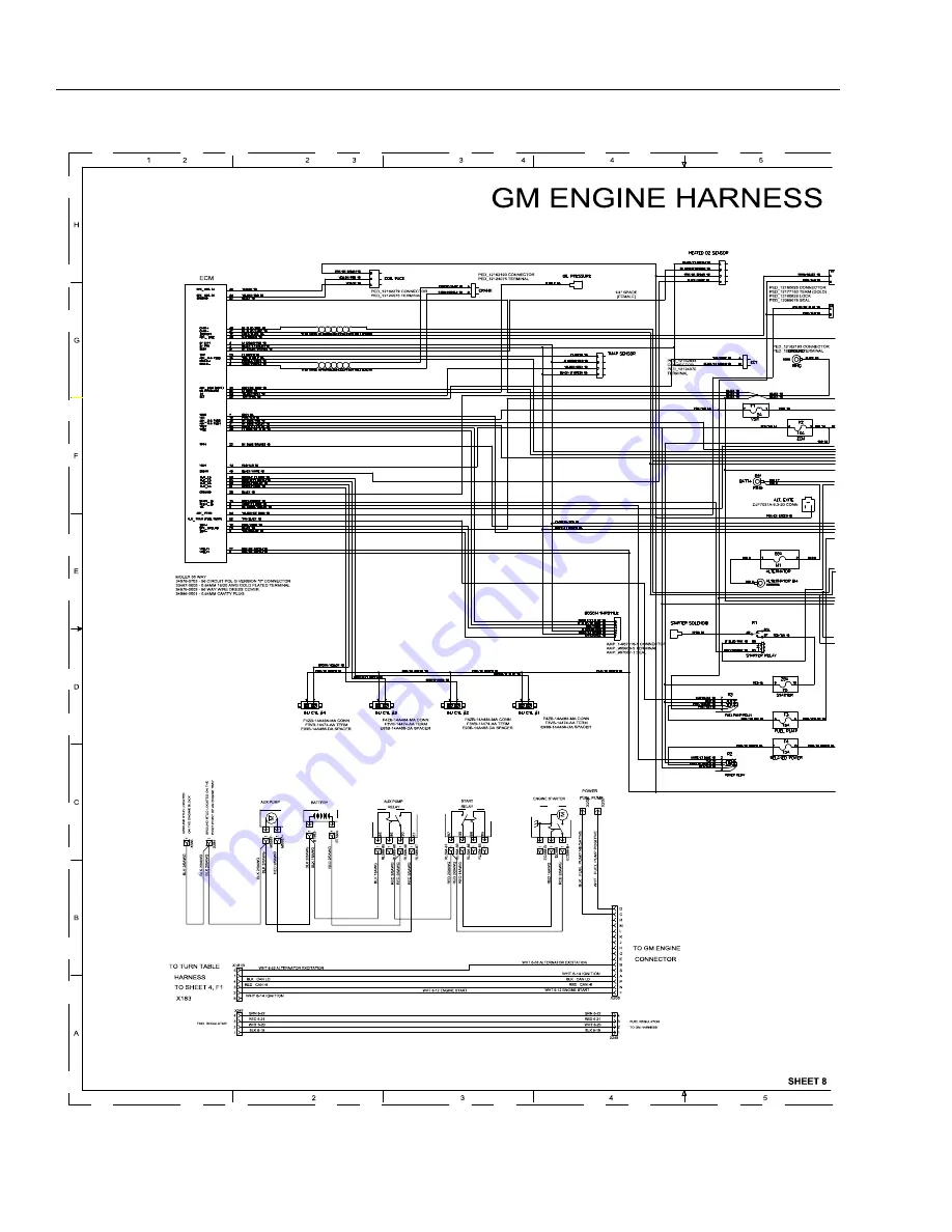
Page 314: ...SECTION 7 BASIC ELECTRICAL INFORMATION ELECTRICAL SCHEMATICS 7 90 JLG Lift 3121659 Figure 7 95 GM Engine Harness Sheet 1 of 3...

Page 315: ...SECTION 7 BASIC ELECTRICAL INFORMATION ELECTRICAL SCHEMATICS 3121659 JLG Lift 7 91 Figure 7 96 GM Engine Harness Sheet 2 of 3...

Page 316: ...SECTION 7 BASIC ELECTRICAL INFORMATION ELECTRICAL SCHEMATICS 7 92 JLG Lift 3121659 Figure 7 97 GM Engine Harness Sheet 3 of 3...

Page 317: ...SECTION 7 BASIC ELECTRICAL INFORMATION ELECTRICAL SCHEMATICS 3121659 JLG Lift 7 93 Figure 7 98 Chassis Head and Tail Lights Harness Sheet 1 of 5...

Page 318: ...SECTION 7 BASIC ELECTRICAL INFORMATION ELECTRICAL SCHEMATICS 7 94 JLG Lift 3121659 Figure 7 99 Chassis Head and Tail Lights Harness Sheet 2 of 5...

Page 319: ...SECTION 7 BASIC ELECTRICAL INFORMATION ELECTRICAL SCHEMATICS 3121659 JLG Lift 7 95 Figure 7 100 Chassis Head and Tail Lights Harness Sheet 3 of 5...

Page 320: ...SECTION 7 BASIC ELECTRICAL INFORMATION ELECTRICAL SCHEMATICS 7 96 JLG Lift 3121659 Figure 7 101 Chassis Head and Tail Lights Harness Sheet 4 of 5...

Page 321: ...SECTION 7 BASIC ELECTRICAL INFORMATION ELECTRICAL SCHEMATICS 3121659 JLG Lift 7 97 Figure 7 102 Chassis Head and Tail Lights Harness Sheet 5 of 5...

Page 322: ...SECTION 7 BASIC ELECTRICAL INFORMATION ELECTRICAL SCHEMATICS 7 98 JLG Lift 3121659 Thispageleftblankintentionally...

Page 323: ...ACE M AIN VALVE UPPER UPRIGHT GROUND CONTROL PANEL SHEET 6 ENGINE SCHEM ATIC DEUTZ T4I DEUTZ ENGINE T4I T4i ENG POS T4i ENG NEG POS BATTERY NEG BATTERY AUX TO AUX SHEET 7 ENGINE SCHEM ATIC DEUTZ T4F D...

Page 324: ...25 26 27 28 29 30 31 32 33 34 35 C O 01 J6 1 2 3 4 5 6 7 8 C O 01 J2 1 2 3 4 5 6 7 8 9 10 11 12 13 14 15 16 17 18 19 20 21 22 23 24 25 26 27 28 29 30 31 32 33 34 35 C O 01 J8 1 2 C O 01 J5 1 2 3 4 5...

Page 325: ...SECTION 7 BASIC ELECTRICAL INFORMATION ELECTRICAL SCHEMATICS 3121659 JLG Lift 7 101 1001157930 C Figure 7 105 Electrical Schematic Sheet 3 of 17...

Page 326: ...SECTION 7 BASIC ELECTRICAL INFORMATION ELECTRICAL SCHEMATICS 7 102 JLG Lift 3121659 1 1 A B C D E F G H Figure 7 106 Electrical Schematic Sheet 4 of 17...

Page 327: ...SECTION 7 BASIC ELECTRICAL INFORMATION ELECTRICAL SCHEMATICS 3121659 JLG Lift 7 103 1001157930 c Figure 7 107 Electrical Schematic Sheet 5 of 17...

Page 328: ...SECTION 7 BASIC ELECTRICAL INFORMATION ELECTRICAL SCHEMATICS 7 104 JLG Lift 3121659 Figure 7 108 Electrical Schematic Sheet 6 of 17...

Page 329: ...SECTION 7 BASIC ELECTRICAL INFORMATION ELECTRICAL SCHEMATICS 3121659 JLG Lift 7 105 1001157930 C Figure 7 109 Electrical Schematic Sheet 7 of 17...

Page 330: ...SECTION 7 BASIC ELECTRICAL INFORMATION ELECTRICAL SCHEMATICS 7 106 JLG Lift 3121659 Figure 7 110 Electrical Schematic Sheet 8 of 17...

Page 331: ...SECTION 7 BASIC ELECTRICAL INFORMATION ELECTRICAL SCHEMATICS 3121659 JLG Lift 7 107 1001157930 C Figure 7 111 Electrical Schematic Sheet 9 of 17...

Page 332: ...SECTION 7 BASIC ELECTRICAL INFORMATION ELECTRICAL SCHEMATICS 7 108 JLG Lift 3121659 Figure 7 112 Electrical Schematic Sheet 10 of 17...

Page 333: ...SECTION 7 BASIC ELECTRICAL INFORMATION ELECTRICAL SCHEMATICS 3121659 JLG Lift 7 109 1001157930 C Figure 7 113 Electrical Schematic Sheet 11 of 17...

Page 334: ...SECTION 7 BASIC ELECTRICAL INFORMATION ELECTRICAL SCHEMATICS 7 110 JLG Lift 3121659 Figure 7 114 Electrical Schematic Sheet 12 of 17...

Page 335: ...SECTION 7 BASIC ELECTRICAL INFORMATION ELECTRICAL SCHEMATICS 3121659 JLG Lift 7 111 1001157930 C Figure 7 115 Electrical Schematic Sheet 13 of 17...

Page 336: ...SECTION 7 BASIC ELECTRICAL INFORMATION ELECTRICAL SCHEMATICS 7 112 JLG Lift 3121659 Figure 7 116 Electrical Schematic Sheet 14 of 17...

Page 337: ...SECTION 7 BASIC ELECTRICAL INFORMATION ELECTRICAL SCHEMATICS 3121659 JLG Lift 7 113 1001157930 C Figure 7 117 Electrical Schematic Sheet 15 of 17...

Page 338: ...SECTION 7 BASIC ELECTRICAL INFORMATION ELECTRICAL SCHEMATICS 7 114 JLG Lift 3121659 Figure 7 118 Electrical Schematic Sheet 16 of 17...

Page 339: ...SECTION 7 BASIC ELECTRICAL INFORMATION ELECTRICAL SCHEMATICS 3121659 JLG Lift 7 115 SHEET 9 1001157930 c Figure 7 119 Electrical Schematic Sheet 17 of 17...

Page 340: ...SECTION 7 BASIC ELECTRICAL INFORMATION ELECTRICAL SCHEMATICS 7 116 JLG Lift 3121659 NOTES...

Page 341: ......

Page 342: ...erhude Ihlpohl Germany 49 0 421 69350 0 49 0 421 69350 45 Email german parts jlg com JLG Equipment Services Ltd Rm 1107 Landmark North 39 Lung Sum Avenue Sheung Shui N T Hong Kong 852 2639 5783 852 26...

Reviews:

Related manuals for JLG 450AJ