794380D / 0914
2. GETTING STARTED
35
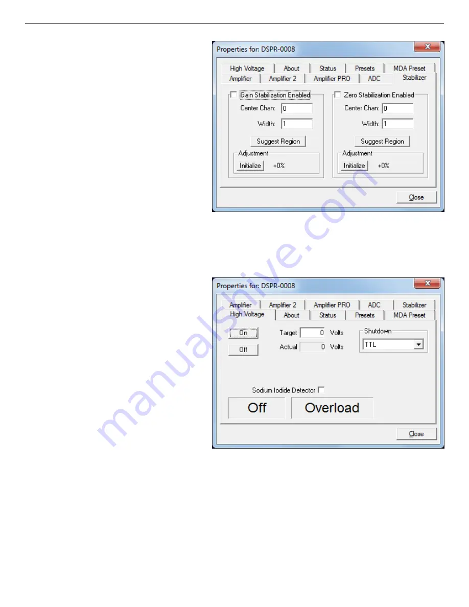
Figure 19. DSPEC Pro Stabilizer Tab.
Figure 20. DSPEC Pro High Voltage Tab.
To enable the stabilizer, enter the
Center Channel and Width values
manually or click the Suggest
Region button. Suggest Region
reads the position of the marker and
inserts values into the fields. If the
marker is in an ROI, the limits of the
ROI are used. If the marker is not in
an ROI, the center channel is the
marker channel and the width is 3×
the FWHM at this energy. Now
click the Enabled checkbox to turn
the stabilizer on. Until changed in
this dialog, the stabilizer will stay
enabled even if the power is turned
off. When the stabilizer is enabled, the Center Channel and Width cannot be changed.
2.3.6. High Voltage
Figure 20 shows the High Voltage
tab, which allows you to turn the high
voltage on or off; set and monitor the
voltage; and choose the Shutdown
mode.
The shutdown can be TTL, ORTEC,
or SMART. The ORTEC mode is
used for all ORTEC detectors except
SMART-1 detectors. Use the SMART
option for those detectors. Check with
the detector manufacturer for other
detectors. The TTL mode is used for
most non-ORTEC detectors.
The polarity is determined by the
DIM or SMART-1 module, which also supplies the bias voltage. The recommended HV for
SMART-1 is displayed on the dialog. For other detectors, see the detector manual or data sheet
for the recommended voltage.
Enter the detector high voltage in the Target field, click On, and monitor the voltage in the
Actual field. Click the Off button to turn off the high voltage. The HV will not turn on if the
detector is sending a remote shutdown or overload signal. The Overload indicator means there
Summary of Contents for DSPEC Pro
Page 4: ...iv Intentionally blank...
Page 9: ...ix Intentionally blank...
Page 10: ...x...
Page 106: ...DSPEC Pro Digital Gamma Ray Spectrometer User s Manual 794380D 0914 96 Intentionally blank...
Page 108: ...DSPEC Pro Digital Gamma Ray Spectrometer User s Manual 794380D 0914 98 Intentionally blank...


