7
Installation
Prior to Installation
Locate the Fireplace
Keep the following factors in mind when selecting a location for the fireplace:
Fireplace clearance requirements (review “General Clearances” sections).
Heat release and air intake requirements (review “Heat Release” and “Air Intake” sections).
Adequate space for servicing.
Access panel recommendations (review “Access Panel” section).
Minimum vertical vent rise, allowed horizontal lengths, and degree of offset (review “Venting” section).
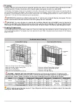
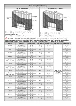
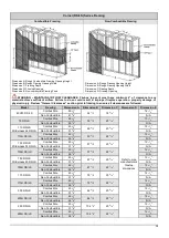
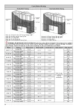
Framing and finishing requirements (review “Framing” and “Finishing” sections).
Front wall installation and finishes to be completed after fireplace and vent installation (review “Step-By-Step Chase
Construction” section).
Floor or Platform requirements (review “Platform” section).
Fireplace Installation
Use the following guidelines to ensure a smooth installation. The installation sequence is divided into three phases: Planning,
Installation, and Startup.
First Trip to Site: Planning
Consult with the contractor and go over all requirements:
Chase framing requirements.
5
/
8
” Type X Drywall (or equivalent) requirements.
Heat release requirements.
Air Intake requirements (if applicable).
Access panel size and location.
Gas and electric specs and location.
Vent configuration.
Finishing details.
NOTE: Provide the contactor with a printed copy of the “Building Checklist” and review requirements with them.
Second Trip to Site: Installation
Confirm the following items are properly located and built to specification:
Framing (with
5
/
8
” Type X Drywall)
Platform
Gas and electric
Access panel (if applicable)
Heat release
Air intake (if applicable)
Clear a path free of any possible obstruction to carry in the fireplace.
Uncrate the fireplace and set in place.
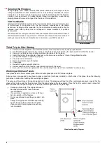
Secure the fireplace by attaching the seismic brackets to the framing. See “Securing the Fireplace” section below.
Remove plastic sleeve covering pilot tube and electrical wires.
Remove all zip ties.
Optional: Remove gas and electrical components from metal shipping plate if desired.
Move the components to the access panel location. Be mindful of the routing for future service needs.
Connect the light grounding cable to the fireplace leg closest to the access panel.
Install the vent components. See “Vent Installation” section below.
Review the front wall requirements (see “Step-By-Step Chase Construction” section) and finishing details with the contractor.
Protect the fireplace and components from damage.
WARNING: HANDLING SPACE CREATOR FIREPLACES
The Space Creator fireplace must be handled with care due to its special and sensitive shape. Do not remove the securing brackets
before installation. After removing the securing brackets, the appliance must be treated with care to maintain its leveled shape. Do
not shake, throw, stand, or put weight on it.
WARNING: LIP INSTALLATION IN H FIREPLACES
To ensure the glass is removable after installation, Magnetic Screw (Part #M03) under the fireplace lip
must
be secured tightly to the
firebox and screwed in as far as possible prior to installation of framing and finish material. If the magnet is not completely screwed
down into the firebox, the lip will sit ajar to the firebox, preventing glass removal.
Summary of Contents for Clear 130 LS
Page 53: ...53 Wiring Diagram Screen Fireplace with Interior Lighting...
Page 54: ...54 Wiring Diagram Screen Fireplace with Interior Lighting and Ortal Power Vent...
Page 55: ...55 Wiring Diagram Double Glass Fireplace...
Page 56: ...56 Wiring Diagram Double Glass Fireplace with Interior Lighting...
Page 57: ...57 Wiring Diagram Double Glass Fireplace with Interior Lighting and Ortal Power Vent...
Page 58: ...58 Carbon Monoxide Detector Wiring Diagrams CO Kit Wiring Diagram Screen Fireplace...
Page 59: ...59 CO Kit Wiring Diagram Double Glass Fireplace...


