background image

31 

Step-by-Step Chase Construction 

The following checklist is a simplified overview of typical chase construction for a built-in  fireplace  installation. This list is not 

exhaustive and does not supplement thorough review of the installation manual. 

Step 1 

BUILD BACK AND SIDE WALLS 

Frame the back and side walls according to framing requirements.

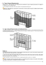
  For Traditional series fireplaces with combustible framing, cover the combustible framing on the inside of the chase with

5/8” Type X Drywall (or equivalent). 

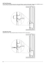
Build the platform (if necessary) to the desired height and install inside fireplace chase.

  Platform must be stable and able to bear the full weight of the fireplace. Platform can be constructed out of wood, concrete,

metal, or any other solid materials. Material is not required to be non-combustible. 

Step 2 

INSTALL FIREPLACE AND VENTING, RUN GAS AND ELECTRICAL 

Install the fireplace and venting. This must be completed by an authorized Ortal dealer (unless otherwise authorized by Ortal

with written approval).

Move the gas valve and receiver unit to the designated access panel location. If the fireplace will not have an access panel,

keep gas valve and receiver unit directly underneath the fireplace. (Skip this step for Traditional series fireplaces.)

Run gas and electric to the gas valve and receiver unit location.

Step 3 

BUILD FRONT WALL 

Install front chase wall:

  Build front wall according to framing requirements.

  Stand up the front wall and move into place.

  Secure front wall to the rest of the chase structure.

Cover the exterior of each wall (sides and front, and back if applicable depending on your design) with 

5

/

8

” Type X Drywall (or

equivalent) and seal gaps with a non-combustible fire sealant.

 NOTE: 

5

/

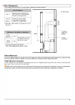
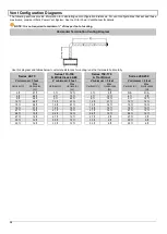
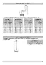
8

” Type X Drywall (or equivalent) is not required on the exterior portion of an insulated outside-facing wall. 

Check to make sure constructed chase meets heat release and air intake (if applicable) requirements.

Step 4 

APPLY FINISHES 

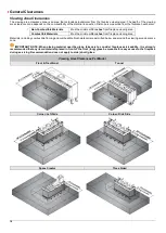
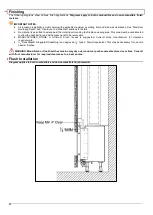
Apply finishes and install accessories, following all clearances and building requirements.

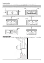
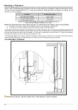
Ensure furniture and other combustible materials maintain a minimum 36 inches of clearance directly in front of the fireplace

viewing area for both front and side viewing areas (as applicable).

Summary of Contents for Clear 130 LS

Page 1: ...ilt In Models V3 Installation and Operation Manual Built In Models Built In Models Front Facing Traditional Corner RS LS Tunnel Three Side Space Creator Curve Island Wilderness Manufacturer Update Ser...

Page 2: ...geways of the fireplace must be kept clean Any alteration to the product can cause soot or carbon to form and may result in damage This damage and any other damage that results from not following the...

Page 3: ...a TV Artwork 26 Access Panel 28 Chase Area Minimum 29 Recessed Ledge Detail 29 Structural Weight Support 30 Step by Step Chase Construction 31 Finishing 32 Flush Installation 32 Recessed Installation...

Page 4: ...place Certified to US Standard CLASS 2901 04 DOMESTIC HEATERS GAS Vented Fireplace The fireplaces are permitted for indoor use only Indoor is defined as a conditioned space The fireplaces are not appr...

Page 5: ...F RS LS TS TN Island 130 100 Single US ANSI Z21 88 2016 Canada CSA 2 33 2016 Natural Gas or Propane 5 x8 Co axial Direct Vent 44 51 60 Wilderness 44 F RS LS TS Wilderness 51 F RS LS TS Wilderness 60...

Page 6: ...rating label with the fireplace in an area easily accessible by the owner typically near the access panel if available You must instruct the owner before handing over the fireplace where this label c...

Page 7: ...ming with 5 8 Type X Drywall Platform Gas and electric Access panel if applicable Heat release Air intake if applicable Clear a path free of any possible obstruction to carry in the fireplace Uncrate...

Page 8: ...s and clean the inside of the fireplace Install the Interior Design Media if desired on the burner as specified in Interior Design Media section Confirm the fireplace is operating properly Check remot...

Page 9: ...turn and perform the final inspection which includes Cleaning the glass with a ceramic glass cleaner otherwise the white residue will remain Checking the interior media setup Checking for gas leaks Ad...

Page 10: ...fireplace viewing area must always be non combustible framing Maintain min 1 4 clearance from front face of fireplace and front metal off set to the framing Maintain min 4 space between air vents at t...

Page 11: ...raming Dimensions The following diagrams are for illustrative purposes only There are multiple approved installation scenarios A flush application is not the only permitted application The fireplace m...

Page 12: ...ible 45 1 8 37 3 4 18 15 3 8 Non Combustible 29 7 8 N A 75x65 F Combustible 53 3 8 38 3 8 18 15 1 8 Non Combustible 38 3 8 N A 60x80 F Combustible 57 29 3 8 18 1 8 14 5 8 Non Combustible 42 1 2 N A 11...

Page 13: ...n Combustible 41 3 8 N A 75 RS LS Combustible 46 3 4 35 1 4 20 1 8 13 1 4 Non Combustible 33 1 2 N A 110 RS LS Wilderness 44 RS LS Combustible 43 5 8 50 3 4 20 5 8 12 1 2 Non Combustible 31 1 8 N A 11...

Page 14: ...s 14 3 8 Non Combustible 41 1 4 N A 75x65 TN Combustible 53 3 8 38 3 8 19 1 8 15 1 8 Non Combustible 38 3 8 N A 60x80 TN Combustible 57 29 3 8 19 1 8 14 5 8 Non Combustible 42 3 8 N A 110 TN Combustib...

Page 15: ...stop dimensions 14 1 8 Non Combustible 41 3 8 N A 75 TS Combustible 38 3 4 33 5 8 20 1 8 13 1 4 Non Combustible 33 1 2 N A 110 TS Wilderness 44 TS Combustible 43 5 8 49 20 5 8 12 1 2 Non Combustible 3...

Page 16: ...imum 4 of clearance to any material achieve sufficient airflow Failure to do so could result in improper fireplace operation property damage or physical injury Review General Clearances section prior...

Page 17: ...additional layer of 5 8 Type X Drywall is required to line the inside of the chase as well Platform The fireplace must be installed on a flat solid continuous surface Surface can be wood concrete meta...

Page 18: ...st be minimum 36 inches from fireplace viewing area Materials including combustible flooring and combustible finish material are permitted below and around the viewing area clearance zone IMPORTANT NO...

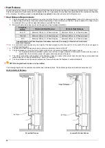
Page 19: ...g on the model to any material Firebox Clearance Per Model Front Traditional Tunnel Corner Left Side Corner Ride Side Space Creator Three Side Clearance to Ceiling Maintain a 12 inch clearance from th...

Page 20: ...rebox is required Framing and or building material is NOT permitted in this area Doing so will block the air vents on the fireplace and cause the entire surrounding to overheat Framing Clearance Maint...

Page 21: ...does not apply to a wall that is constructed in front of the viewing area For materials that will be in front of a main or side viewing area please refer to the Viewing Area Clearances section NOTE Th...

Page 22: ...0 Minimum 250 sq in of free air space Minimum 325 sq in of free air space Includes Built In Curve Island fireplaces Heat release requirements do not apply to Stand alone Curve stand alone Island firep...

Page 23: ...release is oriented vertically Entire heat release is on one side of the fireplace chase Split Front Vertical Heat Release Full Vertical Heat Release on One Side Sprinkler Clearance to Heat Release In...

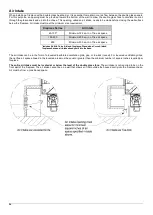
Page 24: ...sq in of free air space 250 Minimum 250 sq in of free air space Includes Built In Curve Island fireplaces Stand alone Curve Island fireplaces have an air intake already built into the base The air in...

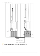
Page 25: ...25 Air Intake for a Platform NOTE Please refer to the Platform section for details on platform construction...

Page 26: ...d prevent heat damage Mount the TV or artwork a minimum of 12 inches above the top of the fireplace viewing area TV wires must be routed through framing and cannot pass through the fireplace chase The...

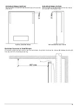
Page 27: ...ecess is 3 3 4 inches A deeper recess will interfere with required clearances to venting Maximum possible recess increases at 12 inches above the viewing area when venting is offset as shown in diagra...

Page 28: ...lation fireplace dealers installers should work with the owner builder project architects and or interior designers to determine the best size and location of their access panel If an access panel can...

Page 29: ...he top of a fireplace that is less than 24 inches 48 inches for Traditional series from the top of the fireplace viewing area must maintain a minimum of 12 inches from the top of the viewing area to t...

Page 30: ...face Consult with the project structural engineer and refer to your local building codes for proper wall support The following drawing shows a recommended approach to this type of installation Please...

Page 31: ...ove the gas valve and receiver unit to the designated access panel location If the fireplace will not have an access panel keep gas valve and receiver unit directly underneath the fireplace Skip this...

Page 32: ...viewing area This area must be unobstructed to allow the heat barrier and inside glass panel to be removable MANUFACTURED STONE A minimum 2 inch recess is suggested Consult stone manufacturer for cle...

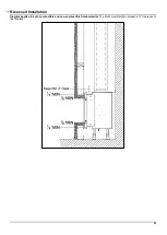
Page 33: ...33 Recessed Installation Diagram applies to both combustible and non combustible finish material The finish must maintain at least a 1 8 clearance to the fireplace...

Page 34: ...axial direct vent pipe 5 inch interior 8 inch exterior Olympia Ventis DuraVent Direct Vent Pro ICC EXCELDirect BDM Pro Form Direct Vent System Selkirk Direct Temp System Enervex Power Vent see note b...

Page 35: ...Island and Curve fireplaces See Offset Maximum Exception below Offset Maximum Up to 180 of offset elbows can be used in the vent configuration If the vent configuration exceeds this maximum consider a...

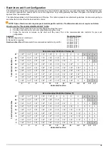
Page 36: ...Traditional Series 200 250 V minimum 3 feet V minimum 3 feet V minimum 3 feet V minimum 6 feet Vertical V Max Horizontal H Vertical V Max Horizontal H Vertical V Max Horizontal H Vertical V Max Horiz...

Page 37: ...6 ft 3 ft 10 ft 18 ft 10 ft 18 ft 10 ft 15 ft 10 ft 12 ft 13 ft 18 ft 13 ft 15 ft 13 ft 12 ft 13 ft 12 ft 16 ft 18 ft 16 ft 15 ft 16 ft 12 ft 16 ft 12 ft 19 ft 15 ft 19 ft 12 ft 19 ft 12 ft 19 ft 12 f...

Page 38: ...feet so the H length is 27 feet Per the table the restrictor plate is 0 No restrictor is required SCENARIO C The vent configuration has one 90 offset The first 90 offset is not taken into calculation...

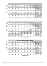
Page 39: ...Represents the recommended restrictor by width Restrictor Sizes 20mm 0 79 30mm 1 18 40mm 1 57 50mm 1 97 60mm 2 36 80mm 3 15 Recommended Restrictor Series 40 Total Vertical Vent Rise 27 1 97 1 57 1 57...

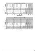
Page 40: ...18 0 x x x x 21 1 97 1 97 1 97 1 57 1 18 1 18 1 18 0 0 x x x 18 1 97 1 97 1 97 1 57 1 18 1 18 1 18 0 0 0 x x 15 1 97 1 97 1 57 1 57 1 18 1 18 1 18 x 0 0 0 x 12 1 57 1 57 1 57 1 57 1 18 1 18 1 18 x 0...

Page 41: ...8 0 0 0 x x x x 6 1 97 1 57 1 57 1 18 0 0 0 x x x x x 3 x x x x x x x x x x x x 0 3 6 9 12 15 18 21 24 27 30 33 Horizontal Vent Run Recommended Restrictor Series 250 Total Vertical Vent Rise 27 x x x...

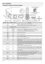
Page 42: ...3 feet minimum between termination caps 2 All mechanical air intakes within 10 feet of a termination cap must be a minimum of 3 feet below the termination cap 3 All gravity air intakes within 3 feet...

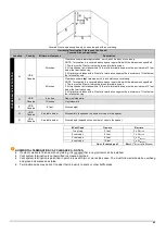
Page 43: ...within 10 feet of a termination cap must be a minimum of 3 feet below the termination cap 3 All gravity air intakes within 3 feet of a termination cap must be a minimum of 1 foot below the terminatio...

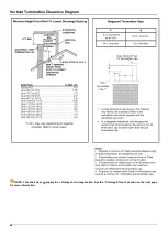
Page 44: ...44 Vertical Termination Clearance Diagram NOTE This chart does not apply to a chimney shroud application See the Chimney Shroud section on the next page for more information...

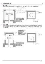
Page 45: ...ding above and below the cap Sides Open Keep a minimum 6 inch clearance around the diameter of the cap s side edge and a minimum 10 inch clearance above the top of the cap For openings in the shroud m...

Page 46: ...th Co linear flexible aluminum venting must be professionally inspected periodically for corrosion and damage and replaced when necessary If the installation does not allow for future inspection or re...

Page 47: ...se 10 feet see diagram below Maximum Vertical Rise 40 feet see diagram below Offsets Two 45 offsets may be used directly on the fireplace with up to a 6 foot section between them The minimum vertical...

Page 48: ...55 000 650 Front 800 Rear Standard Double Propane 11 0 13 0 10 0 17 265 53 238 160 Front 220 Rear 110 120 130 100 Single Natural Gas 5 0 10 0 5 6 22 798 37 167 1200 Propane 11 0 13 0 10 0 25 113 35 3...

Page 49: ...off valve and a 12 gas flex connector are provided with every fireplace The location of the gas shut off valve is dependent on local codes and requirements Check with your authority having jurisdicti...

Page 50: ...Electrode Target Type D36 Orifice NG G121 Main Burner Gas Fitting G02 Mertik Gas Valve G25 Burner Gas Tube G301 Symax Receiver G19 Pilot Gas Tube G202 XRGB Symax Wi Fi Box G34 Spark Plug Connector G2...

Page 51: ...ouble glass heat barrier power vent or a heat control system may not be used with batteries Pairing the Remote and Receiver To set up the remote control device to operate the fireplace follow the foll...

Page 52: ...52 Wiring Diagrams The following diagrams show the electrical wiring required for different feature combinations Wiring Diagram Screen Fireplace...

Page 53: ...53 Wiring Diagram Screen Fireplace with Interior Lighting...

Page 54: ...54 Wiring Diagram Screen Fireplace with Interior Lighting and Ortal Power Vent...

Page 55: ...55 Wiring Diagram Double Glass Fireplace...

Page 56: ...56 Wiring Diagram Double Glass Fireplace with Interior Lighting...

Page 57: ...57 Wiring Diagram Double Glass Fireplace with Interior Lighting and Ortal Power Vent...

Page 58: ...58 Carbon Monoxide Detector Wiring Diagrams CO Kit Wiring Diagram Screen Fireplace...

Page 59: ...59 CO Kit Wiring Diagram Double Glass Fireplace...

Page 60: ...ss logs and embers that can provided with the fireplace This section provides guidelines for safe placement of media It is crucial that the placement guidelines outlined below are followed as a large...

Page 61: ...l injury Do not use the hood to support media This could cause overheating of the thermocouple Keep the media away from the edges and the glass Do not overfill the media tray Keep 20 of the tray open...

Page 62: ...w ports as possible If a log is placed over a port block the port with a coin to keep the flame from creating soot on the media or to manipulate the look of the flame Block as few ports as possible an...

Page 63: ...will be affected when handset is in use Operating Instructions Instructions for operating the 10 Button Handset are shown below For more in depth instructions please refer to the Homeowner s Fireplac...

Page 64: ...se flame height or to set fireplace to pilot flame only press and hold the button Wall Switch Operating Instructions Turning the Fireplace On Off ON Press and hold the ON OFF button until two short be...

Page 65: ...ated within 26 feet of the receiver NOTES For detailed App setup and operating instructions refer to the Homeowners Operation and Maintenance Guide www myfireapp com The myFire Wi Fi box is required f...

Page 66: ...e removed ONLY by an authorized Ortal dealer service technician The Ortal dealer service technician should ONLY remove the glass with the suction cup supplied by the manufacturer Lower the glass to re...

Page 67: ...Ortal 2021 Version 3 March 2021 SKU KPMANUALUS3 0 Ortal USA 8421 Canoga Ave Canoga Park CA 91304 T 818 238 7000 F 818 678 0541 info ortalheat com www ortalheat com...

Reviews: