Orientalmotor OPX-2A Operating Manual Download Page 38

10 Copy mode


38


10 Copy mode 

The 

OPX-2A

 has four data banks, and operation data and parameters can be saved in each of these data 

banks. Since an EEPROM is used as the data memory element, stored data will be retained even after the 
power is turned off. 
In the copy mode, you can download data saved in the 

OPX-2A

 to the driver. You can also upload data 

saved in the driver to the 

OPX-2A

It is also possible to verify data in the 

OPX-2A

 against the corresponding data in the driver, or revert 

driver data to their initial values. 

10.1 What you can do in the copy mode 

• 

Download 

Copy data saved in the 

OPX-2A

 to the driver. 

• 

Upload 

Copy data saved in the driver to the 

OPX-2A

• 

Verification 

Verify data in the 

OPX-2A

 against the corresponding data in the driver. 

• 

Initializing driver data 

Revert data saved in the driver to their initial values. 

10.2 Operation in the copy mode 
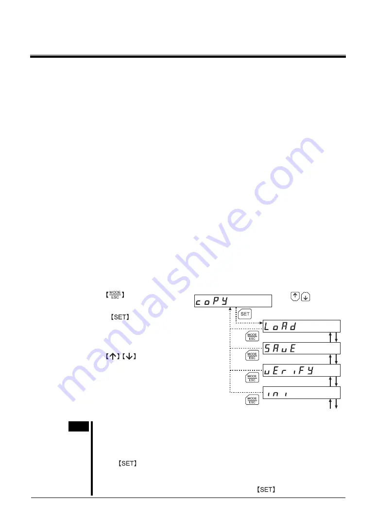
1. 

Use the 

  key to select the 

copy mode. 

2. 

Press the 

  key in the top 

screen of the copy mode. 

The display changes to the copy mode 
item screen. 

3. 

Use the 


  keys to select 

the item you want to perform. 

Download

Top screen of the copy mode

Download

Upload

Verification

Initialization

Use

to navigate

through the items.


Note 

• 

Stop the motor operation before changing to the copy mode. 

• 

When you move from the top screen of the copy mode to a lower level, the START 
input, FWD input, RVS input, HOME-P/PRESET input and M0 to M5 inputs will be 
disabled. 

• 

If the 

  key on the 

OPX-2A

 is pressed while internal processing is being 

performed via RS-485 communication, the top screen will not change to any of its 
sub-screens and “mEm-bUSY” will be shown on the display. Be sure to wait until all 
internal processing is completed, before pressing the 

 key. 

Summary of Contents for OPX-2A

Page 1: ...r OPERATING MANUAL Thank you for purchasing an Oriental Motor product This Operating Manual describes product handling procedures and safety precautions Please read it thoroughly to ensure safe operat...

Page 2: ...21 7 3 Initializing operation data 21 8 Parameter mode 22 8 1 Types of parameters 22 8 2 Operation in the parameter mode 23 8 3 Setting example 24 8 4 Description of application parameters 25 I O para...

Page 3: ...or injury Assign qualified personnel the task of installing wiring operating controlling inspecting and troubleshooting the product Failure to do so may result in fire electric shock or injury When th...

Page 4: ...he driver Features of OPX 2A The OPX 2A can be used not only to set driver operation data and parameters but it also serves as a storage location for driver data Driver data is saved in the areas call...

Page 5: ...larms etc LED indicators These LED indicators are used to indicate the operation mode of the OPX 2A and the driver status Use this button to change the operation mode or move to the upper level Use th...

Page 6: ...ed or an alarm or warning generates a corresponding LED will be lit While the motor is operating or the edit lock function is enabled the condition is also indicated by the illumination of a correspon...

Page 7: ...icator currently lit 3 6 Edit lock function Enable the edit lock function if you want to prevent operation data and parameters from being edited or cleared Operation data and parameters cannot be chan...

Page 8: ...ction in the test mode press the key to select the test mode indicated by a lit TEST LED The top screen of the test mode is displayed Press the key to move to the lower level Use the keys to select a...

Page 9: ...1 Press the key once to move to the 100 s digit you want to edit 4 Press the key to change the value to 1 5 Next change the sign Press the key once to move to the sign digit you want to edit 6 Press...

Page 10: ...sun Area free of excessive amount of dust iron particles or the like Area not subject to splashing water rain water droplets oil oil droplets or other liquids Area free of excessive salt Area not sub...

Page 11: ...connector CN3 Driver Note When operation data and parameters are set on the OPX 2A they will be stored in the driver Once stored in the driver the data will not be cleared even after the OPX 2A is dis...

Page 12: ...est Download Motor rotation direction I O Command position JOG operation Upload Stepout detection Present alarm Verify Common Present warning Position preset Encoder counter preset Teaching Positionin...

Page 13: ...records presetting the position preset the encoder counter teaching and perform operations in the copy mode To data No selection 1 To download Operation Return to home Return to home operation To mot...

Page 14: ...tails of the alarm warning Up to ten most recent alarms warnings can be displayed starting from the latest one You can reset the alarms currently present You can clear alarm warning records Checking I...

Page 15: ...y selected Present alarm When an alarm generates a corresponding alarm code will be displayed You can also reset alarms or check and clear alarm records Note Do not turn off the driver power while an...

Page 16: ...items If operations are limited by the edit lock function p 7 the screen text in gray is not shown Alarm code list Code Alarm name Resetting on the OPX 2A Number of times the driver s ALARM LED blinks...

Page 17: ...d Use the keys to select the warning record you want to check How to clear all warning records You can clear all warning records at once 1 While a warning is displayed press the key to move to the low...

Page 18: ...monitor Output monitor to navigate through the items Use Each bar on the 7 segment LED corresponds to each signal When the photo coupler of a given signal is ON the corresponding bar is lit When the p...

Page 19: ...e driver Note Operation data has significant bearing on motor operation Before setting any operation data make sure you fully understand the content of the operation data If operations are limited by...

Page 20: ...e edit lock function p 7 the screen text in gray is not shown Note If the value you have input is outside the setting range Error will be displayed for 1 second If this error display appears input a d...

Page 21: ...ration and continuous operation Operating mode 0 0 Single 1 Link Sets perform positioning operation as single motion or linked motion operation Sequential positioning 0 0 Disable 1 Enable Sets enable...

Page 22: ...I O Set the parameters relating to I O signals Motor Set the parameters relating to motor Speed Set the parameters relating to speed Return to home Set the parameters relating to return to home opera...

Page 23: ...ey again to move to the parameter item screen 4 Use the keys to select the parameter you want to change Application parameters I O Motor Operation Motor rotation direction System parameters Stepout de...

Page 24: ...n parameter screen 3 Press the key The display changes to the START input mode parameter screen 4 Use the key to select 6 The display changes to the OUT1 signal mode selection parameter screen 5 Press...

Page 25: ...TIM 7 READY 8 WNG 9 HOME P 10 ZSG 11 R OUT1 12 R OUT2 13 STEPOUT Sets the function assigned to the OUT4 output 0 0 HOME 1 P PRESET Sets whether to use HOME or P PRESET input 1 0 RS 485 communication 1...

Page 26: ...n to take place upon the occurrence of overtravel 0 8 388 608 to 8 388 607 steps Sets the preset position 0 8 388 608 to 8 388 607 steps 0 8 388 608 to 8 388 607 steps Sets the range for AREA output T...

Page 27: ...n deceleration rate in positioning operation and continuous operation 100 1 to 500 000 Hz Sets the starting speed in positioning operation and continuous operation 1000 1 to 500 000 Hz Sets the operat...

Page 28: ...ection for home detection 0 0 Disable 1 Enable Sets whether or not to concurrently use the SLIT input for return to home operation 0 0 Disable 1 Enable TIM 2 Enable ZSG Sets whether or not to concurre...

Page 29: ...the deviation angle between the command position and encoder counter value 31 0 25 0 to 35 0 V Sets the condition at which an overheat warning generates 85 40 to 85 C 104 to 185 F Sets the condition...

Page 30: ...timeout occurs 0 0 Function disable 0 01 to 9 99 sec Sets the receive period for RS 485 communication 50 0 to 1000 ms Sets the response period for RS 485 communication 0 10 0 01 to 9 99 sec Sets the r...

Page 31: ...r step angle Encoder electronic gear A Encoder electronic gear B through the items Use to navigate Motor step angle parameters Setting Step angle Number of divisions Setting Step angle Number of divis...

Page 32: ...tus of the driver JOG operation You can operate the motor using the keys on the OPX 2A Positioning operation You can performe the positioning operation Return to home operation You can performe the re...

Page 33: ...to the test mode When you move from the top screen of the test mode to a lower level the STARTinput FWD input RVS input HOME P PRESET input and M0 to M5 inputs will be disabled What happens when the k...

Page 34: ...2 through the items Use to navigate Indicates the OFF status Indicates the ON status to navigate through the digits Use to switch the ON OFF status Use Each bar on the 7 segment LED corresponds to ea...

Page 35: ...dangerous situations Operation is in progress Top screen of JOG operation Pressing once causes the motor to rotate one step in the direction Pressing and holding the key causes the motor to rotate con...

Page 36: ...y Top screen of return to home operation 9 7 Presetting the position In this operation the command position is preset by rewriting the value in the preset position parameter APP 0 21 Note If operation...

Page 37: ...nding settings applicable to JOG operation Note During teaching the motor rotates at the specified operating speed Before commencing teaching consider the status of the equipment and condition of its...

Page 38: ...driver Initializing driver data Revert data saved in the driver to their initial values 10 2 Operation in the copy mode 1 Use the key to select the copy mode 2 Press the key in the top screen of the...

Page 39: ...e shown Be sure to cancel the edit lock before pressing the key Refer to p 7 for the procedure to cancel the edit lock 10 3 Downloading to the driver In this operation data in the specified data bank...

Page 40: ...nload again If the same error occurs the data saved in the OPX 2A may be damaged Upload the applicable data to set the OPX 2A data again The specified data bank number does not contain data Check the...

Page 41: ...ication error occurs a code indicating the nature of the error will blink on the display Verification will not be performed and the display will return to the top screen of verification Blinking displ...

Page 42: ...s blinking display Processing is in progress blinking display Processing is in progress blinking display Processing is in progress blinking display Use through the items to navigate Note System parame...

Page 43: ......

Page 44: ...eir respective companies and are hereby acknowledged The third party products mentioned in this manual are recommended products and references to their names shall not be construed as any form of perf...

Reviews: