USER MANUAL
DVI MATRIX ROUTER
– ODM1818
ODM1818 Manual - Edition 7a
Page 8
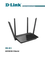
Figure 1-3 Concept drawing for setting EDID in ODM1818
As depicted in Figure 1-3, once EDID is configured, each EDID is stored in EEPROM at
the front of the DVI Input. As a result, the video sources are able to read EDID from the
EEPROM during boot-up; even though the ODM1818 and connected displays are not
powered on yet.
1.6 Connecting Optical DVI cables and modules for extended distance
ODM1818 supports connection of Optical DVI cables or modules to all inputs and outputs.
The use of copper DVI cables over 3m (10ft.) is not recommended.
1.7 Initializing ODM1818 and Installation Guide
1.7.1
Initialization
1) Plug the provided AC power cord to the AC/DC power adaptor then plug the DC
cord to the +12VDC connector on the rear panel; make sure that the arrow mark
on the connector of the DC cord is aligned.
2) Push POWER button on the front panel then observe:
EEPROM18
EEPROM1
EEPROM2
EEPROM17
EEPROM3
EEPROM16
EDID
INTERFACE
CONTROL
INPUT 1~`18
OUTPUT 1~18
WRITE EDID