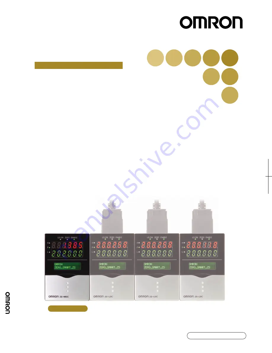
background image

©

OMRON Corporation 2004

        All Rights Reserved.

Note: Specifications subject to change without notice.

Printed in Japan.

0804-1M (A)

Authorized Distributor:

Cat. No. Z209-E1-01

OMRON Corporation
Industrial Automation Company

Application Sensors Division
Sensing Devices and Components Division H.Q.
Shiokoji Horikawa, Shimogyo-ku,
Kyoto, 600-8530 Japan
Tel: (81)75-344-7068/Fax: (81)75-344-7107

Regional Headquarters
OMRON EUROPE B.V.
Sensor Business Unit,
Carl-Benz-Str. 4, D-71154 Nufringen,
Germany
Tel: (49)7032-811-0/Fax: (49)7032-811-199

OMRON ELECTRONICS LLC
1 East Commerce Drive, Schaumburg, IL 60173
U.S.A.
Tel: (1)847-843-7900/Fax: (1)847-843-8568

OMRON ASIA PACIFIC PTE. LTD.
83 Clemenceau Avenue,
#11-01, UE Square,
239920 Singapore
Tel: (65)6835-3011/Fax: (65)6835-2711

OMRON CHINA CO., LTD. BEIJING OFFICE
Room 1028, Office Building,
Beijing Capital Times Square,
No. 88 West Chang’an Road,
Beijing, 100031 China
Tel: (86)10-8391-3005/Fax: (86)10-8391-3688

Smart Sensor

Multi-Controller

ZS-MDC (Ver 2.0)

User's Manual

Cat. No. Z209-E1-01

Cat.

 No.

 Z209-E1-01

ZS-MDC Smar

t Sensor

s Multi-Contr

oller

User's Man

ual

Multi-Controller

Summary of Contents for ZS-MDC

Page 1: ...Smart Sensor Multi Controller ZS MDC Ver 2 0 User s Manual Cat No Z209 E1 01 Cat No Z209 E1 01 ZS MDC Smart Sensors Multi Controller User s Manual Multi Controller ...

Page 2: ... in electrical engineering To ensure correct use please read this manual thoroughly to deepen your understanding of the product Please keep this manual in a safe place so that it can be referred to whenever necessary How to Switch the Display Language to English Turn the power ON with the MENU key held down This displays the display language selection screen If you change and save the setting the ...

Page 3: ...ection 3 Section 4 Section 5 INTRODUCTION SECTION 1 SECTION 2 SECTION 3 SECTION 4 SECTION 5 Section APPLICATION CONSIDERATIONS Please Read FEATURES INSTALLATION CONNECTION SETUP APPLICATION SETTING EXAMPLES APPENDIX User s Manual Smart Sensors Multi Controller ZS MDC ...

Page 4: ... ALONE HAS DETERMINED THAT THE PRODUCTS WILL SUITABLY MEET THE REQUIREMENTS OF THEIR INTENDED USE OMRON DISCLAIMS ALL OTHER WARRANTIES EXPRESS OR IMPLIED LIMITATIONS OF LIABILITY OMRON SHALL NOT BE RESPONSIBLE FOR SPECIAL INDIRECT OR CONSEQUENTIAL DAMAGES LOSS OF PROFITS OR COMMERCIAL LOSS IN ANY WAY CONNECTED WITH THE PRODUCTS WHETHER SUCH CLAIM IS BASED ON CONTRACT WARRANTY NEGLIGENCE OR STRICT ...

Page 5: ...tems aviation systems medical equipment amusement machines vehicles safety equipment and installations subject to separate industry or government regulations Systems machines and equipment that could present a risk to life or property Please know and observe all prohibitions of use applicable to the products NEVER USE THE PRODUCTS FOR AN APPLICATION INVOLVING SERIOUS RISK TO LIFE OR PROPERTY WITHO...

Page 6: ... proofreading errors or omissions PROGRAMMABLE PRODUCTS OMRON shall not be responsible for the user s programming of a programmable product or any consequence thereof COPYRIGHT AND COPY PERMISSION This document shall not be copied for sales or promotions without permission This document is protected by copyright and is intended solely for use in conjunction with the product Please notify us before...

Page 7: ...d power devices 2 Power Supply and Wiring The supply voltage must be within the rated range DC24V 10 Reverse connection of the power supply is not allowed Open collector outputs should not be short circuited Use the power supply within the rated load High voltage lines and power lines must be wired separately from this product Wiring them together or placing them in the same duct may cause inducti...

Page 8: ... oil or chemical fumes or spray Strong magnetic or electric field 2 Power Supply and Wiring When using a commercially available switching regulator make sure that the FG ter minal is grounded If surge currents are present in the power lines connect surge absorbers that suit the operating environment Before turning ON the power after the product is connected make sure that the power supply voltage ...

Page 9: ...inutes before use The circuits are still unstable immediately after the power supply is turned ON so measured values may fluctuate gradually 5 Maintenance and Inspection Do not use thinner benzene acetone or kerosene to clean the Multi Controller Right Wrong Wrong To improve heat radiation install the Multi Controller only in the orientation shown below Do not install the Multi Controller in the f...

Page 10: ...NPUT D input D Assigns the target Sensor Controller to input D Range None 1CH onwards largest CH of gang mounted Sensor Controllers default 4CH Note that range becomes None if 4CH does not exist Setting Logic Operation Methods Set how logic operations are to be performed on the tasks and CH specified by the assignment settings FUNMODE SENSING CALC Inputs do not undergo logical operation when None ...

Page 11: ...n and windows dialog boxes and other GUI elements displayed on the PC are indicated enclosed by brackets aa Visual Aids Indicates points that are important to ensure full product performance such as operational precautions and application procedures Indicates pages where related information can be found Indicates information helpful in operation ...

Page 12: ...10 Introduction ZS MDC User s Manual Introduction Editor s Note MEMO ...

Page 13: ... 1 About Installation and Connection 2 2 Multi Controller 2 3 Attaching the ferrite core 2 3 Installing the Multi Controller 2 4 About the I O cable 2 10 Section 3 SETUP 3 1 Setting Flow 3 2 About Setup 3 4 Basic Knowledge for Operation 3 4 List of Setting Items 3 9 Selecting Tasks 3 13 Setting the Sensor Controller to Obtain Sensing Information from 3 14 Setting Assignments 3 14 Setting Logic Ope...

Page 14: ...8 Measuring Flatness 4 10 Measuring the Average Height 4 12 Measuring the Twist of a Workpiece 4 14 Measuring the Warp of a Workpiece 4 17 Section 5 APPENDIX 5 1 Troubleshooting 5 2 Error Messages and Countermeasures 5 3 Q A 5 4 Glossary 5 5 Specifications and External Dimensions 5 6 Multi Controller 5 6 Panel Mount Adapters 5 9 RS 232C Cable for Connecting to a Personal Computer 5 10 Controller L...

Page 15: ...Section 1 FEATURES 1 1 ZS MDC User s Manual Section 1 FEATURES Multi Controller Features 1 2 Multi Controller Applications 1 4 Basic Configuration 1 7 Part Names and Functions 1 8 ...

Page 16: ...up to nine Sensor Controllers which makes the Multi Controller ideal for multi point measurement applications 2 Wide Range of Logic Operation Functions Dedicated expressions such as sandwiched thickness step and average are provided in the setup menu Up to four types of expressions can be stored to memory as tasks which allows you to easily achieve multi point measurement applications for performi...

Page 17: ...ing of logic operations matched to specific applications List of Setup Items p 3 9 5 USB Connection A USB port Full Speed USB2 0 specification compliant is provided as standard on the Multi Controller This enables the results of operations between Sensor Controllers to be easily loaded to a personal computer 6 Dedicated Software SmartMonitor Zero The SmartMonitor Zero software for setting up and m...

Page 18: ...ns can be performed not only on one location but on multiple loca tions to calculate the difference in the measurement result Measurement of Stepped Workpieces Logic operations can be performed on measured values obtained from multiple Sensor Controllers to measure steps in stepped workpieces Measurement of Average Workpiece Height Logic operations can be performed on measured values obtained from...

Page 19: ...performed on measured values obtained from multiple Sensor Controllers to measure the waviness flexure twist and warp of steel plate and other workpieces Batch acquisition of Multi point Measurement Data Communications commands can be used to batch acquire the measurement results of gang mounted Sensor Controllers About Digital Output p 3 17 You can also use the optional software SmartMonitor Zero...

Page 20: ... Controllers can be set up The measurement conditions of each Sensor Controller can be set up and settings saved read or copied The state of gang mounted Sensor Controllers can be monitored The operating state of each Sensor Controller can be batch monitored The waveforms of each Sensor Controller can be displayed simultaneously The screen shown here may differ from the actual screen The screen sh...

Page 21: ...S2 RS 232C cable for personal computer connection DC24V 10 Recommended parts 1 When 1 Sensor Controller is connected S82K 01524 DC24V 0 6 A 2 When 2 to 3 Sensor Controllers are connected S82K 05024 DC24V 2 1 A 3 When 4 to 10 Sensor Controllers are connected Prepare the required number of 1 and 2 power supplies above Power Supply USB cable 1m This is used for communicating with a personal computer ...

Page 22: ...eeded when the Sensor Head is not connected or when measurement is not being performed in the FUN mode 4 Main Display The Main Display shows measured values after operations have been performed 5 Sub display The sub display shows thresholds and additional information during measurement 6 LCD screen RUN mode Displays additional information for the main display and the setup menu for display related...

Page 23: ...ld is satisfied 12 HIGH indicator The HIGH indicator lits when the condition HIGH threshold measured value is satisfied 13 Coupler This connector is for connecting the Multi Controller to the Sensor Controller 14 RS 232C connector Connect the RS 232 cable when you are connecting the Multi Controller to a personal computer that does not have a USB port 15 Voltage Current switch The Voltage Current ...

Page 24: ...1 10 Section 1 FEATURES ZS MDC User s Manual Section 1 Part Names and Functions MEMO ...

Page 25: ...N CONNECTION 2 1 ZS MDC User s Manual Section 2 INSTALLATION CONNECTION About Installation and Connection 2 2 Multi Controller 2 3 Attaching the ferrite core 2 3 Installing the Multi Controller 2 4 About the I O cable 2 10 ...

Page 26: ...g of this manual and check the instal lation environment Checking the installation site Read Precautions for Correct Use at the beginning of this manual and check the installation site About the power supply Before installing and connecting the Multi Controller be sure to turn it OFF Also read Precautions for Safe Use and Precautions for Correct Use at the begin ning of this manual and check the p...

Page 27: ...ction of the I O cable Before connecting disconnecting peripheral devices make sure that the Multi Controller is turned OFF The Multi Controller may break down if the Multi Controller is connected or disconnected while the power is ON Attaching the ferrite core Attach the ferrite core provided with the Multi Controller to the I O cable of the Multi Controller Ferrite core ...

Page 28: ... Sensor Controller and Sensor Heads refer to the User s Manual for the Sensor Controller Provide power to all connected Sensor Controllers About channel No when controllers are gang mounted When performing operation from SmartMonitor Zero or an external device select the controller to be set up by its channel No The following shows how channel Nos are assigned when Sensor Controllers are gang moun...

Page 29: ...ok the connector end of the Sensor Controller onto the DIN track 2 Push the Multi Controller down onto the DIN track until the hook on the I O cable side is locked Push down until you hear it snap into place Always hook the connector end of the Multi Controller on the DIN track first Hooking the I O cable end on the DIN track first may impair the mounting strength of the DIN track attachment DIN t...

Page 30: ...ntroller to insert to the Controller Link Unit connector Removal procedure The following describes how to remove the Multi Controller and Sensor Controller from the DIN track 1 Slide and remove the Sensor Controller from the connector on the Controller Link Unit 2 Slide the Controller Link Unit and remove from the connector on the Multi Controller 3 Install the cover on the coupler of the controll...

Page 31: ...TION CONNECTION Section 2 Multi Controller 2 7 ZS MDC User s Manual 4 Pull the hook on the I O cable end downwards 5 Lift up the Sensor Controller from the I O cable end and remove it from the DIN track Hook on I O cable ...

Page 32: ... Controller and Sensor Controller from the rear of the panel towards the front 3 Install the small Mount Adapters on the four holes on the Multi Controller and Sensor Controller Install the small Mount Adapters on all gang mounted Multi Controllers and Sensor Controllers H LD ON ZE RO EN AB LE P L H LD ON ZE RO EN AB LE P L H LD ON ZE RO EN AB LE P L H LD ON ZE RO EN AB LE P L H LD ON ZE RO EN AB ...

Page 33: ...nto the two holes of the small Mount Adapters and tighten the screws Attach two mounting fixtures each on all gang mounted Multi Controllers and Sensor Controllers 7 Make sure that the Multi Controller and Sensor Controllers are firmly fixed on the panel H LD ON ZE RO EN AB LE P L H LD ON ZE RO EN AB LE P L H LD ON ZE RO EN AB LE P L H LD ON ZE RO EN AB LE P L H LD ON ZE RO EN AB LE P L H LD ON ZE...

Page 34: ...iring them together or placing them in the same duct may cause induction resulting in malfunction or damage Supply power simultaneously to all gang mounted controllers to be used When power is turned ON individually the channels will not be recognized normally 2 GND The GND terminal is the 0V power supply terminal When using a Multi Controller with an NPN output the GND terminal is also the common...

Page 35: ...g input signal assignments can be selected Signal assignments Setting I O Assignments p 3 16 Signal functions For details on the timing charts of external I O refer to User s Manual for the Sensor Controller Signal When Standard is selected default When Bank is selected IN0 External trigger timing input Bank input A IN1 Reset input Bank input B IN2 Unused Unused IN3 Zero reset input Zero reset inp...

Page 36: ...ck Pink Gray Co axial black Shielded Load Load Load Load Load Load DC24V OUT0 OUT1 OUT2 OUT3 OUT4 GND 0V DC24V Yellow Light blue Purple White IN0 IN1 IN2 IN3 Orange Linear output Linear GND Current output 300Ω or less Voltage output 10 kΩ or more Current voltage output selector switch Current output 4 to 20 mA Internal circuits Voltage output 10 V 40 Ω ...

Page 37: ...V Red Green Black Pink Gray OUT0 OUT1 OUT2 OUT3 OUT4 Blue GND 0V Yellow Light blue Purple White IN0 IN1 IN2 IN3 Orange Load Load Load Load Load Co axial black Shielded Linear output Linear GND Load Current output 300 Ω or less Voltage output 10 kΩ or more Current voltage output selector switch Current output 4 to 20 mA Voltage output 10 V 40Ω ...

Page 38: ...2 14 Section 2 INSTALLATION CONNECTION ZS MDC User s Manual Section 2 About the I O cable MEMO ...

Page 39: ...ng Items 3 9 Selecting Tasks 3 13 Setting the Sensor Controller to Obtain Sensing Information from 3 14 Setting Assignments 3 14 Setting Logic Operation Methods 3 15 Setting I O Assignments 3 16 Switching banks by external signal input 3 16 Changing Output Assignments 3 17 Changing Linear Output Assignments 3 17 About Digital Output 3 17 ...

Page 40: ...ng Set how measured information is to be processed for outputting the required values Set the filter conditions for processing measured information Setting Filter Function Sensor Controller User s Manual Section 3 Setup Sensor Controller User s Manual Section 3 Setup Sensor Controller User s Manual Section 3 Setup Sensor Controller User s Manual Section 3 Setup Sensor Controller User s Manual Sect...

Page 41: ...3 Setup Sensor Controller User s Manual Section 3 Setup Sensor Controller User s Manual Section 3 Setup When a Problem Occurs The Multi Controller does not operate correctly Troubleshooting Want to know the meanings of terms Glossary An error message has appeared When Error is Displayed on the Main Display Setting Banks Set up the banks Set up the system environment Set Up the System Environment A...

Page 42: ...ZS MDC has the following 3 operating modes Switch to the desired mode before you start operation To switch the operating mode use the Mode Switch When you switch the operating mode after changing the measurement conditions you will be prompted to save the settings Save the settings as required If you turn off the Multi Controller with out saving these settings the newly set measurement conditions ...

Page 43: ...ages by the LEFT or RIGHT key Key Operations Key FUN Mode Function keys Directly sets the No preceding the items displayed on the LCD screen LEFT key RIGHT key The function changes depending on the settings Scrolls pages in list menus Selects the digit of numerical values Main Display LCD screen Sub display Control keys Alphabet characters that appear on the digital displays The currently selected...

Page 44: ...yed flashing 3 Press function key 2 representing ON The Complete message is displayed 4 Press the MENU key to return to the top menu Pressing the ESC key returns to the previous menu UP key DOWN key Changes numerical values during numerical value input MENU key Displays the top menu of the FUN mode SET key Applies the item you are setting up ESC key Returns to the previous menu Key FUN Mode 1SENSI...

Page 45: ...ording to the setting of the current voltage switch Values displayed here are reference values only These values differ from actual linear output values RESOLU Displays the fluctuation width peak to peak of the measured value over a fixed amount of time DISTANCE Displays the measured value before it is processed by hold or other functions Key Measured Value Display Display Customize Menu Function ...

Page 46: ...he display customize menu SET key Executes a zero reset Applies numerical value settings ESC key Hold down for at least two sec onds to cancel a zero reset Returns to the previous menu When the top menu is displayed returns to the measured value display Key TEACHING DIRECT IN Function keys Not used Not used LEFT key RIGHT key Not used Selects the digit in the threshold numerical value UP key DOWN ...

Page 47: ... selected all items including items common to all tasks can be set When a task other than TASK1 is selected only items specific to that task can be set When TASK1 is selected Settings Default Value Option Range Pages SENSING SEL CH Input A to input I p 3 14 CALC CH OFF CH input A to input I CALC THICK STEP K mX nY AVE MAX MIN p 3 15 FILTER SMOOTH ON OFF ON AVERAGE 1 1 2 4 8 16 32 64 128 256 512 10...

Page 48: ...1 to TASK4 NONE DIGITAL LOG1 to 9 NONE INPUT A to INPUT I TASK1 to TASK4 BANK CHANGE BANK1 BANK1 BANK2 BANK3 BANK4 CLEAR Initializes bank settings SYSTEM SAVE Saves Multi Controller settings INIT Initializes Multi Controller settings INFO CYCLE Displays the current measurement cycle VERSION Displays the Multi Controller version COM RS 232C LENGTH 8BIT 8BIT 7BIT PARITY NONE NONE ODD EVEN STOP 1BIT ...

Page 49: ...mX nY AVE MAX MIN p 3 15 FILTER SMOOTH ON OFF ON AVERAGE 1 1 2 4 8 16 32 64 128 256 512 1024 2048 4096 DIFF OFF OFF ON OUTPUT SCALING OFF OFF ON AUTO MAN HOLD TYPE OFF OFF PEAK BOTTOM P P AVERAGE SAMPLE TRIGGER EXT EXT SELF UP SELF DN DELAY OFF OFF ON T DELAY T TIME 0RESET TYPE REAL REAL HOLD OFFSET 0 999 99 to 999 999 BANK same as when TASK1 is selected SYSTEM same as when TASK1 is selected FUN M...

Page 50: ...the MENU key in the RUN mode TEACH Mode This is the mode for setting the threshold values Settings Default Value Option Range Page s DIGITAL DOT 3 0 to 5 ECO NORMAL NORMAL ECO OFF LCD ON OFF ON ON AUTOOFF OFF B LIGHT ON ON AUTOOFF OFF CUSTOM U OFF D OFF U ON OFF L ON OFF Upper section customize lower section customize HELP Settings Default Value Option Range Page s TEACHING DIRECT IN RUN mode TEAC...

Page 51: ...o you want to display The currently selected task is displayed as TKX on the LCD display The items that can be set in the FUN mode change according to the currently selected task When TASK1 is selected all items including items common to all tasks can be set When a task other than TASK1 is selected only items specific to that task can be set Items common to all tasks are as fol lows SEL CH NO MEAS...

Page 52: ...if 3CH does not exist INPUT D input D Assigns the target Sensor Controller to input D Range None 1CH onwards largest CH of gang mounted Sensor Controllers default 4CH Note that range becomes None if 4CH does not exist INPUT E input E Assigns the target Sensor Controller to input E Range None 1CH onwards largest CH of gang mounted Sensor Controllers default 5CH Note that range becomes None if 5CH d...

Page 53: ...kness input the mode changes to the measurement mode and the current thickness value is displayed on the main dis play For this reason during thickness input enter in a measurement ready state STEP X Y Select this item to set step measurement step measurement Xrange input A to input I TASK1 to TASK4 Yrange input A to input I TASK1 to TASK4 K mX nY Select this to perform logic operations on X and Y...

Page 54: ...ut state changes At most it takes about 10 seconds to switch banks During bank switching the BUSY output becomes ON Setting Description TASK Select to task for enabling the external signal lead Note however that reset input and bank inputs affects tasks at all times Range TASK1 to TASK4 TASK ALL FUNC NORMAL Select this to use external input function as in standard applications so far default value...

Page 55: ...utput from the Multi Controller Setting Description NONE Input A to input I TASK1 to TASK4 Set this to batch output multiple data to external devices using CompoWay F or non procedural commands Assign to log 1 to 9 inputs A to I or TASK1 to 4 to be output When a command is input the inputs or tasks are output continuously in order from log 1 to 9 The data of the nine channels can be batch output w...

Page 56: ...3 18 Section 3 SETUP ZS MDC User s Manual Section 3 Setting I O Assignments MEMO ...

Page 57: ...asuring the Thickness of Multiple Points sandwiched thickness 4 2 Measuring the Relative Difference between Steps 4 5 Measuring the Reference Difference between Steps 4 8 Measuring Flatness 4 10 Measuring the Average Height 4 12 Measuring the Twist of a Workpiece 4 14 Measuring the Warp of a Workpiece 4 17 ...

Page 58: ...nd MAX MIN are used as the operation modes For details on how to connect and install the Sensor Heads and Sensor Controllers refer to the ZS L User s Manual FUN Mode SENSING SEL CH 1 Assign the CH No of the controller to inputs A to F to be used for the expression INPUT A 1CH INPUT B 2CH INPUT C 3CH INPUT D 4CH INPUT E 5CH INPUT F 6CH Thickness Input A Input C Input B Input D Input E Input F Input...

Page 59: ...ct THICK 6 Enter the thickness of the workpiece The thickness of the workpiece you placed is displayed on the LCD Enter the thickness value referring to the displayed value 7 Press the SET Key to apply the setting 8 Following the same procedure as 2 to 7 set up TASK2 and TASK3 TASK2 Enter C to input X and D to input Y TASK3 Enter E to input X and F to input Y 1TASK1 3TASK3 2TASK2 4TASK4 1INPUT X 3...

Page 60: ...alculating the differ ence to ON and other tasks to OFF To output the judgment result of the operation I OSET I O SET OUT 11 Select TASK4 so that the judgment on the thickness difference can be output To linear output the operation result I O SET I O SET ANALOG 11 Select TASK4 so that the thickness differ ence can be linear output The calculation results of each CH can be batch acquired if you use...

Page 61: ...ression For details on how to connect and install the Sensor Heads and Sensor Controllers refer to the ZS L User s Manual FUN Mode SENSING SEL CH 1 Assign the CH No of the controller to inputs A to C to be used for the expression INPUT A 1CH INPUT B 2CH INPUT C 3CH Press MENU key ESC key 2 Select TASK1 Input B Input C CH0 CH1 CH2 CH3 Input A Input B Input C The operation and or measurement results...

Page 62: ...UT X INPUT C INPUT Y INPUT A To output the judgment result of the operation I O SET I O SET OUT 6 Select TASK1 TASK2 or TASK3 depending on the details to be output To output judgment on the difference between point A and point B Set TASK1 to I O SET To output judgment on the difference between point B and point C Set TASK2 to I O SET To output judgment on the difference between point C and point A...

Page 63: ...epending on the details to be output To output judgment on the difference between point A and point B Set TASK1 to I O SET To output judgment on the difference between point B and point C Set TASK2 to I O SET To output judgment on the difference between point C and point A Set TASK3 to I O SET The calculation results of each CH can be batch acquired if you use the communication command 1TASK1 3TAS...

Page 64: ...r two locations Use STEP X Y for the expression For details on how to connect and install the Sensor Heads and Sensor Controllers refer to the ZS L User s Manual FUN Mode SENSING SEL CH 1 Assign the CH No of the controller to inputs A to C to be used for the expression INPUT A 1CH INPUT B 2CH INPUT C 3CH Press MENU key ESC key 2 Select TASK1 Input A Input B Input C Reference difference between ste...

Page 65: ... reference point and point B Set TASK1 to I O SET To output judgment on the difference between point A reference point and point C Set TASK2 to I O SET To linear output the operation result I OSET I O SET ANALOG 5 Select TASK1 or TASK2 depending on the details to be output To output the difference between point A reference point and point B Set TASK1 to I O SET To output the difference between poi...

Page 66: ... on how to connect and install the Sensor Heads and Sensor Controllers refer to the ZS L User s Manual FUN Mode SENSING SEL CH 1 Assign the CH No of the controller to inputs A to I to be used for the expression INPUT A 1CH INPUT B 2CH INPUT C 3CH INPUT D 4CH INPUT E 5CH INPUT F 6CH INPUT G 7CH INPUT H 8CH INPUT I 9CH Input A Input B Input C Input I CH0 CH1 CH2 CH9 CH3 Input A Input B Input C Input...

Page 67: ...ment result of the operation I O SET I O SET OUT 4 Select TASK1 so that the judgment on the flatness measurement can be output To linear output the operation result I O SET I O SET ANALOG 4 Select TASK1 so that the flatness measurement can be linear output The calculation results of each CH can be batch acquired if you use the communication command 1TASK1 3TASK3 2TASK2 4TASK4 1INPUT A 3INPUT C 2IN...

Page 68: ...e For details on how to connect and install the Sensor Heads and Sensor Controllers refer to the ZS L User s Manual FUN Mode SENSING SEL CH 1 Assign the CH No of the controller to inputs A to C to be used for the expression INPUT A 1CH INPUT B 2CH INPUT C 3CH Press MENU key ESC key 2 Select TASK1 Input A Input B Input C Input A Input B Input C CH0 CH1 CH2 CH3 The operation and or measurement resul...

Page 69: ... judgment result of the operation I O SET I O SET OUT 4 Select TASK1 so that the judgment on the average value can be output To linear output the operation result I O SET I O SET ANALOG 4 Select TASK1 so that the average value can be linear output The calculation results of each CH can be batch acquired if you use the communication command 1INPUT A 3INPUT C 2INPUT B 1TASK1 3TASK3 2TASK2 4TASK4 1TA...

Page 70: ...alues Use X Y for the expression For details on how to connect and install the Sensor Heads and Sensor Controllers refer to the ZS L User s Manual FUN Mode SENSING SEL CH 1 Assign the CH No of the controller to inputs A to C to be used for the expression INPUT A 1CH INPUT B 2CH INPUT C 3CH CH0 CH1 CH2 CH3 CH4 Input A Input B Input C Input A Input B Input C Input D Input D The operation and or meas...

Page 71: ...3 Set the expression of TASK1 INPUT X INPUT A INPUT Y INPUT B 4 Following the same procedure as 2 to 3 set up TASK2 INPUT X INPUT D INPUT Y INPUT C 5 Following the same procedure as 2 to 3 set up TASK2 INPUT X TASK 1 INPUT Y TASK 2 1TASK1 3TASK3 2TASK2 4TASK4 1INPUT X 2INPUT Y Input A Input B Input C Input D Input A Input B Input C Input D Input A Input B Input C Input D ...

Page 72: ...on I O SET I O SET OUT 6 Select TASK3 so that the judgment on the twist can be output To linear output the operation result I O SET I O SET ANALOG 6 Select TASK3 so that the twist value can be linear output The calculation results of each CH can be batch acquired if you use the communication command 1TASK1 3TASK3 2TASK2 4TASK4 1TASK1 3TASK3 2TASK2 4TASK4 ...

Page 73: ... taken to be the warp amount Expression Z B A C 2 In the actual setting calculation mode K mX nY is used For details on how to connect and install the Sensor Heads and Sensor Controllers refer to the ZS L User s Manual FUN Mode SENSING SEL CH 1 Assign the CH No of the controller to inputs A to C to be used for the expression INPUT A 1CH INPUT B 2CH INPUT C 3CH Input A Input B Input C CH0 CH1 CH2 C...

Page 74: ...TASK1 SENSING CALC CALC K mX nY 3 Set the expression of TASK1 INPUT K 0 INPUT m 1 INPUT n 1 INPUT X INPUT A INPUT Y INPUT C 4 Following the same procedure as 2 to 3 set up TASK2 INPUT K 0 INPUT m 1 INPUT n 0 5 INPUT X INPUT B INPUT Y TASK1 1TASK1 3TASK3 2TASK2 4TASK4 1INPUT A 3INPUT C 2INPUT B Input A Input B Input C Input A Input B Input C ...

Page 75: ...on I O SET I O SET OUT 5 Select TASK2 so that the judgment on the warp can be output To linear output the operation result I O SET I O SET ANALOG 5 Select TASK2 so that the warp value can be linear output The calculation results of each CH can be batch acquired if you use the communication command 1TASK1 3TASK3 2TASK2 4TASK4 1TASK1 3TASK3 2TASK2 4TASK4 ...

Page 76: ...4 20 Section 4 APPLICATION SETTING EXAMPLES ZS MDC User s Manual Section 4 Measuring the Warp of a Workpiece MEMO ...

Page 77: ... ZS MDC User s Manual Section 5 APPENDIX Troubleshooting 5 2 Error Messages and Countermeasures 5 3 Q A 5 4 Glossary 5 5 Specifications and External Dimensions 5 6 Version Up Information 5 12 INDEX 5 13 Revision History 5 16 ...

Page 78: ...nications with per sonal computer Is the USB cable connected correctly Is the RS 232 cable connected correctly Strange linear output levels Is the voltage current switch on the bottom of the Sensor Controller set to the correct position Has the correct selection voltage current been made in the focus settings Linear output levels can be fine tuned p 1 8 The main display remains on Has a timing inp...

Page 79: ...input and set all channels to a measurable state Display Details Cause Countermeasure LCD screen SYSTEM ERROR CONNECT The controller is not connected Connect the Controller SYSTEM ERROR BANK DATA Bank data in the Sensor Control ler in error Hold the UP key down for 3 sec onds and then hold the DOWN key down for 3 seconds The sensor is turned ON again and restored after the device is initialized SY...

Page 80: ...n attempted when the measured value is outside the measuring range When two point scaling has been executed the distance between the measured values for the two points is not 1 or more of the rated measuring range When focusing is executed an error appears and settings cannot be made Monitor focus settings cannot be made when the distance between the two specified points is not 1 or more of the ra...

Page 81: ... of the currently set functions e g hold has been processed Press the LEFT or RIGHT Key in the RUN mode to display the present value on the sub display p 3 7 Judgment output Judgment output is a general term for the HIGH PASS and LOW outputs Judgment out puts are made in the RUN or TEACH mode based on the display values and the threshold hysteresis width and timer settings SmartMonitor Zero This i...

Page 82: ...tion 5 APPENDIX ZS MDC User s Manual Section 5 Specifications and External Dimensions Specifications and External Dimensions Multi Controller ZS MDC11 MDC41 24 20 13 10 32 90 3 90 90 4 3 52 50 60 10 80 Unit mm ...

Page 83: ...rt circuited with 0V terminal or 1 5 V max OFF Open leakage current 0 1 mA max ON Supply voltage short cir cuited or within supply volt age 1 5 V OFF Open leakage current 0 1 mA max Timing input Sample cycle speci fied when hold func tion is enabled RESET input Reset of hold state Status indicators HIGH orange PASS green LOW orange LDON green ZERO green ENABLE green Segment display Main display 8 ...

Page 84: ... each in six directions up down left right forward backward Ambient temperature Operating 0 to 50 C Storage 15 to 60 C with no icing or condensation Ambient humidity Operating and storage 35 to 85 RH with no condensation Materials Case Polycarbonate PC Weight Approx 280 g excluding packing materials and accessories Item ZS MDC11 ZS MDC41 ...

Page 85: ...ce 10 to 150 Hz 0 7 mm double amplitude 80 min each in X Y and Z directions Shock resistance 300 m s2 3 times each in six directions up down left right forward backward Materials Polycarbonate PC etc Weight Approx 50g Note 1 60 n 12 60 n 122 90 3 13 140 116 1 60 n 8 Panel DIN track Panel Panel Mount Adapter Note 1 Dimensions are shown for a panel thickness of 2 0 mm Panel cutout dimensions n numbe...

Page 86: ...ion resistance 10 to 150 Hz 0 7 mm double amplitude 80 min each in X Y and Z directions Shock resistance 300 m s2 3 times each in six directions up down left right forward backward Materials Cable sheath PVC Weight Approx 50 g 10 1 Fitting 1 2 3 4 5 6 7 8 9 1 NC 2 RD RXD 3 SD TXD 4 NC 5 SG GND 6 NC 7 RS RTS 8 CS CTS 9 NC 1 NC 2 SD TXD 3 RD RXD 4 RS RTS 5 CS CTS 6 NC 7 NC 8 NC 9 SG GND NC 10 Signal...

Page 87: ... to 50 C Storage 15 to 60 C with no icing or condensation Ambient humidity Operating and storage 35 to 85 RH with no condensation Vibration resistance 10 to 150 Hz 0 7 mm double amplitude 80 min each in X Y and Z directions Shock resistance 300 m s2 3 times each in six directions up down left right forward backward Materials Polycarbonate PC etc Weight Approx 10g 4 60 11 50 18 13 40 39 50 Unit mm ...

Page 88: ...d p 3 13 Logic operation can be performed on the information of Sensor Controllers up to nine channels p 3 14 K mX nY that enables average height measurement and flexible formulas on types of logic operations were added p 3 15 The zero reset memory function was added The input signal setup function was added The I O assignment function was added p 3 16 Description of Change Pages RS 232C delimiter...

Page 89: ...ator 1 9 Output 2 10 I I O cable 2 10 I O circuit diagrams 2 13 I O SET 3 16 3 17 INPUT 3 14 K K mX nY CALC 3 15 L Laser indicator 1 8 LCD screen name 3 5 LD ON 1 8 LOG 3 17 LOW indicator 1 9 Output 2 10 M Main Display 3 5 Mode Switch 3 4 Multi Controller Attaching the ferrite core 2 3 Installation 2 4 Part Names 1 8 Specifications and Dimensions 5 6 O OUT 3 17 OUT0 to 4 2 10 Output cable 2 10 P P...

Page 90: ...5 14 Section 5 APPENDIX ZS MDC User s Manual Section 5 Index U USB port 1 9 V Voltage Current switch 1 9 W wiring 2 10 Z Zero reset indicator 1 8 ...

Page 91: ...5 15 ZS MDC User s Manual Section 5 APPENDIX Section 5 Index MEMO ...

Page 92: ...n History Revision History A manual revision code appears as a suffix to the catalog number at the bottom of the front and back covers of this manual Revision code Date Revised contents 01 October 2004 Original production Z209 E1 01 Cat No Revision code ...

Page 93: ...ment or addition to the above warranty See http oeweb omron com or contact your Omron representative for pub lished information 14 Limitation on Liability Etc OMRON COMPANIES SHALL NOT BE LIABLE FOR SPECIAL INDIRECT INCIDENTAL OR CONSEQUENTIAL DAMAGES LOSS OF PROFITS OR PRODUCTION OR COMMERCIAL LOSS IN ANY WAY CONNECTED WITH THE PRODUCTS WHETHER SUCH CLAIM IS BASED IN CONTRACT WARRANTY NEGLIGENCE ...

Page 94: ... the U S A OMRON ELECTRONICS LLC 1 Commerce Drive Schaumburg IL 60173 847 843 7900 For US technical support or other inquiries 800 556 6766 OMRON CANADA INC 885 Milner Avenue Toronto Ontario M1B 5V8 416 286 6465 OMRON ON LINE Global http www omron com USA http www omron com oei Canada http www omron ca ...

Reviews: