


43
LVCN414-SW software Appendix
(continued)
Section Seven
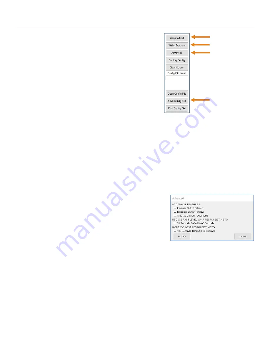
WRITE TO UNIT
After you have entered configurations, selected and
configured the Tank Shape and entered the Tank Values,
click “
Write to Unit
” and load the configuration into the
memory of the sensor. When completed, this configuration
will remain inside the sensor memory and will not change
unless the sensor is connected to LVCN414-SW software
and a new configuration is written to the sensor. Loss of
power will not change or lose the configuration within sensor
memory.
Next, use the file management features to save your
configuration by clicking “
Save Config File
” and print your
wiring diagram by clicking “
Wiring Diagram
.”
Write to Unit
Wiring diagram
Advanced
Save Config File
“
Save Config File
” will save this configuration as a text file which can be loaded back into LVCN414-SW
software by pressing the “
Open Config File
” button. It is good practice to save the configuration file for each
different configuration with a unique name for easy identification. If using multiple sensors in identical
applications, then use of a single configuration file is recommended.
“
Wiring Diagram
” will display a PDF file showing the unique wiring for the specific configuration created in
WebCal™. The PDF can be printed or emailed. It is good practice to save the wiring diagram as a backup
.
“
Advanced
” is a feature setting designed to help solve performance or operational issues for specific
applications. Changing these setting will alter the factory default performance or operation, of your sensor.
Increase Output Filtering
: Placing a check mark in the box will increase the filtering (averaging) of the
analog output. Use this filter if the 4 to 20 mA output requires
a smoother output for the application such as open channel
flow measurement.
Decrease Output Filtering
: Placing a check mark in the box
will eliminate all filtering (averaging) of the analog output
which enables a pulse by pulse level reading. Use this filter to
see changes in level after every echo pulse.
Note:
Never check increase output filtering and decrease output
filtering at the same time.
Stabilize Output in Dead Band
: Placing a check mark in the box will activate a filter to hold the output
at Full if the level enters the dead band of the LVU700 series. This filter requires the level to leave the
dead band at a smooth and steady rate.
Reduce Fast Level Jump Response Time:
Changes the sensor’s response time from 60 seconds to
10 seconds. This filter prevents the sensor from making a quick jump in level if a false signal suddenly
appears. Change the response time if application involves expected quick level changes.
Increase LOST Response Time:
Changes the sensor’s response time from 60 seconds to 180
seconds. This filter sets the time the sensor waits before entering a LOST state. Change the response
time if you want to delay the sensor from stating LOST.


