


HFS Heat Flux Sensor Instruction Manual
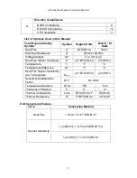
3
Section 1: How to Use a Heat Flux Sensor
Below are details on how to use a heat flux sensor to take thermal measurements. These
directions are for general use and can be somewhat modified depending on the test
conditions in order to collect the most accurate measurements for your application.
Brief Overview of Using the Heat Flux Sensor
1.
Ensure the sensor is operating properly by conducting simple tests of
functionality.
2.
Mount the sensor to the measurement surface.
3.
Connect the heat flux sensor leads and the integrated thermocouple leads to a
precision voltmeter or precision data acquisition device.
4.
Collect measurements by reading the analog DC voltage signals from the wire
leads.
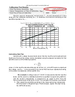
5.
Adjust the sensitivity of the heat
flux sensor according the sensor’s temperature
and the temperature dependence function (not necessary for UHFS-09 sensors).
The sensitivity of the sensor is provided with each unit on their respective
calibration certificate in addition to the temperature dependence function.
6.
Calculate heat flux using the adjusted sensitivity.
7.
Remove the sensor from the measurement surface if necessary while being very
careful not to damage it
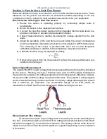
Sensor Signal Measurement
The output of the HFS is a DC voltage that is linearly proportional to the heat flux absorbed
by the sensor. Similarly, the type-T thermocouple used for HFS surface temperature
measurements outputs a DC voltage proportional to the temperature difference between
the sensor surface and the voltage measurement location. The output DC voltage signals
can be measured with any precision voltmeter or 3rd party voltage data acquisition system
with a microvolt,
μV, resolution. The construction design of the HFS allows for
measurement of both heat flux and temperature difference using four wires.
Measuring Heat Flux Voltage
To measure the sensor output voltage that is caused by the sensor absorbing heat
flux, ΔV
q”
, connect the positive (+) terminal of the voltage measurement device to the bright
red wire and negative (-) terminal to the white wire. The polarity of these wires does not
matter too much since heat flux will be positive or negative depending on the orientation
of the sensor.


