background image

Quick Start Guide

Introduction

This guide is designed to help you set up and install the iVu Plus TG and Color Gen2 Image Sensors. For complete information on

programming, performance, troubleshooting, dimensions, and accessories, please refer to the Instruction Manual at 

www.bannerengineering.com

. Search for p/n 179042 to view the Instruction Manual. Use of this document assumes familiarity with

pertinent industry standards and practices.

The iVu includes integrated Help.
See 

www.bannerengineering.com/patents

 for patent information.

WARNING: Not To Be Used for Personnel Protection
Never use this device as a sensing device for personnel protection. Doing so could lead to serious injury or

death. This device does not include the self-checking redundant circuitry necessary to allow its use in

personnel safety applications. A sensor failure or malfunction can cause either an energized or de-energized

sensor output condition.

CAUTION: Electrostatic Discharge
Avoid the damage that electrostatic discharge (ESD) can cause to the Sensor.
Always use a proven method for preventing electrostatic discharge when installing a lens or attaching a cable.

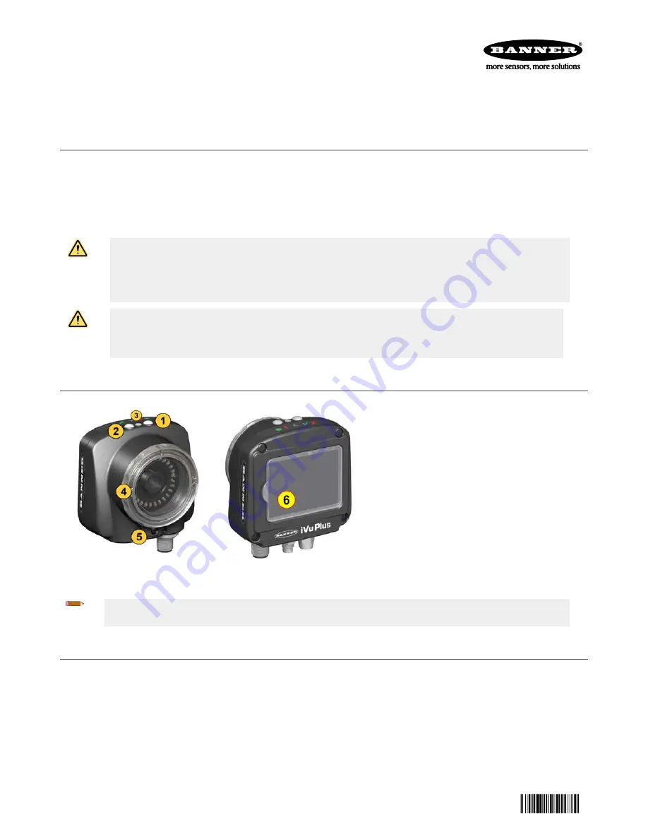
Features and Indicators

Figure 1. Features

1. Power LED

Green: Ready/Power
Red (blinking or steady): Error

2. Pass/Fail LED

Green (steady): Pass
Green (blinking): Error
Red: Fail

3. Ethernet I/O LED

Green: Connected
Off: Disconnected

4. Focusing Window
5. Focusing Window Locking Clip
6. Integrated Display (integrated display

models only)

Note: Integrated display models: The touchscreen display has a plastic cover to protect the display. Remove this
cover when configuring the device. When the display is not in use, keep the display covered to protect it.

Installation Instructions

Mount the 

iVu

The iVu requires a bracket for mounting. Brackets are available from Banner Engineering. See 

www.bannerengineering.com

. The

brackets allow the iVu to be mounted either perpendicular to the part or at an adjustable angle.

1. Position the iVu on the bracket.

iVu Plus TG and Color Gen2 Image Sensors


Original Document

178442 Rev. C

24 April 2018

178442

Summary of Contents for iVu PLUS TG

Page 1: ...N Electrostatic Discharge Avoid the damage that electrostatic discharge ESD can cause to the Sensor Always use a proven method for preventing electrostatic discharge when installing a lens or attachin...

Page 2: ...re Color Description Direction 1 White Output 1 Output 2 Brown 10 V dc to 30 V dc Input 3 Green Output 2 Output 4 Yellow Strobe Out 5 V dc only Output 5 Gray Remote Teach Input 6 Pink External Trigger...

Page 3: ...sensor inspection The green annotations indicate the object passes and the red annotations indicate a failure This sample inspection failed as shown by the red X next to the Display mode button Regio...

Page 4: ...Count Sort Saved Patterns Percent Match Rotation Range Pass Criteria Inspection Name Set Name ID 3 Not available in Match and Sort Inspection Timeout Select Timeout Average Color 1 ROI and Mask Inten...

Page 5: ...cons Icon Description The Main Menu icon is on the bottom left corner of the display on the Home screen Click this icon to access sub menus that are used to set up the iVu The Inspection menu icon is...

Page 6: ...hrough and select a circular elliptical or rectangular shaped mask The Elliptical Mask icon is on the left side of the display when a mask is selected Click this icon to cycle through and select a cir...

Page 7: ...actual objects a Go to Imager White Balance b Move and adjust the white balance Region of Interest ROI to surround a white or gray object in the Field of View FOV If there is none place a piece of wh...

Page 8: ...e separately Adjust the Focus on a C Mount Lens Model 1 Remove the lens enclosure 2 Adjust the focus while monitoring the focus number To ensure the best image adjust the focus until the focus number...

Page 9: ...Sensor Use a Sort sensor to recognize and sort up to ten different patterns within the same inspection Teach each reference pattern during setup Store reference patterns in one of ten pattern memory l...

Page 10: ...milliseconds Note If the interval is less than the inspection time missed triggers will occur Free Run the iVu automatically runs continuous inspections Industrial Ethernet Only only Trigger commands...

Page 11: ...l Ethernet A bi directional communication channel that allows the user to control the device and access device results using Ethernet IP 1 Modbus TCP PCCC or PROFINET 2 protocol Data Export Used to ex...

Page 12: ...it is returned to the factory is found to have been defective during the warranty period This warranty does not cover damage or liability for misuse abuse or the improper application or installation...

Reviews: