
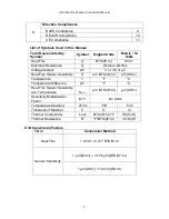
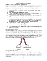


HFS Heat Flux Sensor Instruction Manual
5
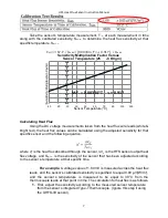
4.
Check the Output Voltage for an Induced Heat Flux Through
Sensor:
A simple method of determining whether the HFS is roughly
operating correctly is by physically inducing a heat flux. Place the HFS
sensor on a metallic surface and firmly placing the palm of your hand across
the entire sensor surface. The resulting peak DC output voltage value
should be somewhere around 1.0 mV for a HFS (this value could vary over
20% from this value depending on the situation). You can also flip the
sensor over and a similar output DC voltage signal with an opposite sign
(positive (+) versus negative (-)) should be measured.
5.
Check the Output Thermocouple Voltage:
If the sensor and voltage measurement location are at equal temperatures, the
output voltage from the thermocouple should be approximately zero microvolts
(this test scenario is often difficult to achieve easily). This test is rarely necessary
since thermocouple electrical resistance should be sufficient enough of a test.
6.
Ensure the Sensor’s Serial Number Matches the Calibration
Certificate
You will want to double check that the heat flux sensor’s serial
number matches that indicted on the Calibration Certificate. This will ensure
that you use the correct sensor sensitivity appropriate for your sensor. The
sensor’s serial number should be located on a tag on the wire leads.
Sensor Mounting/Installation
The manner in which the heat flux sensor is mounted depends on the application that it is
being used for. The best results are obtained from mounting the sensor on smooth clean
surfaces. The overall goal in mounting the HFS is to have the sensor strongly adhered
and fully contacting the measurement surface as uniformly as possible. This reduces the
amount of thermal contact resistance between the measurement surface and the sensor
and thus increases accuracy of measurements. Using one of the following mounting
techniques is recommended but can be adjusted according to the testing setup.
Mounting Method #1: Double-Stick Adhesive Tape
Commercially available double-stick tape is ideal for temporary mounting to solid
surfaces. When using double-stick tape, be sure the measurement surface is
clean, cover the desired mounting area with double sided tape, then firmly & evenly
press the sensor to the tape. If using multiple pieces of double stick tape, avoid
overlapping the tape on itself.
Mounting Method #2: Thermally Conductive Glue
Thermally conductive glue can be used for permanent mounting of the HFS. Before
mounting, clean the measurement surface and the surface of the sensor. Spread
a thin, uniform layer of the thermally conductive glue across the surface of the
sensor. Apply constant, uniform pressure to the sensor until the glue dries.
Removing the sensor from the surface after gluing it will likely destroy the sensor.


