


HFS Heat Flux Sensor Instruction Manual
6
Mounting Method #3: Thermally Conductive Paste
Thermally conductive paste is only appropriate if the sensor is being held in place
with a constant, uniform pressure while the sensor is taking measurements. An
example of an appropriate measurement scenario is if the sensor is used for
conductive heat transfer measurements while being placed between two surfaces
that are squishing it & holding it in place. Thermally conductive paste can be placed
between the sensor and each of the surfaces to minimize thermal contact
resistance. One recommended product is using OmegaTherm 201 conductive
paste available from Omega. Alternatively toothpaste has even been used when
nothing else is available and actually works fairly well.
Another method is to apply a thin layer of thermal conductive paste between the
sensor and the measurement surface. Then use an adhesive tape over the entire
sensor to keep it pressed down onto the surface.
Removing Sensor from Measurement Surfaces
Removing the HFS from the measurement surface is only recommended if a
temporary adhesive such as conductive paste or double-stick tape was used for mounting.
It is possible that higher strength adhesion methods can comprise the integrity of the
sensor if the sensor is removed from them.
IMPORTANT:
When removing the sensor, very carefully remove the side with the leads
with one hand and peel the opposite side with the other hand to avoid bending as much
as possible. Slight bending of the sensor will not affect its performance but ripping it off
surfaces and forcing it to bend sharply should be avoided
Section 2: Converting Measurements to Heat Flux and Temperature
Type T thermocouple temperature measurement
Thermocouple temperature measurements can be recorded with a
thermocouple meter capable of reading T-type thermocouple, with cold junction
compensation. (Suggested meter: Omega DP41-TC)
Temperature Dependence of HFS Heat Flux Sensor
The output signals from HFS-5 and HFS-6 heat flux sensors have some
dependence on the temperature of the sensor itself. This dependence means that
sensor’s sensitivity changes slightly at different temperatures.
UHFS-09 sensors do not
experience this dependence so ignore this section if using this sensor model.
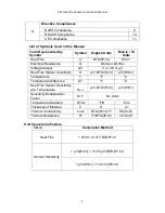
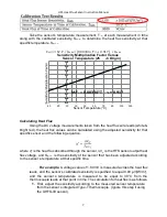
Each sensor is calibrated at a base sensor temperature of 25°C or 77 °F. The
sensitivity at this temperature is recorded on the calibration sheet provided with each
individual heat flux sensor. An example of the calibration sensitivity, S
Calib
, is shown below
circled in red.
If you are using the heat flux sensor at a temperature that is different from 25°C or
77°F then it is suggested that you adjust the sensitivity to compensate for the temperature
dependence using the following steps.


