background image

5699-E P-35

SECTION 3   OPERATION (OF CNC LATHE)

MAS1

LE11214R0100500190002

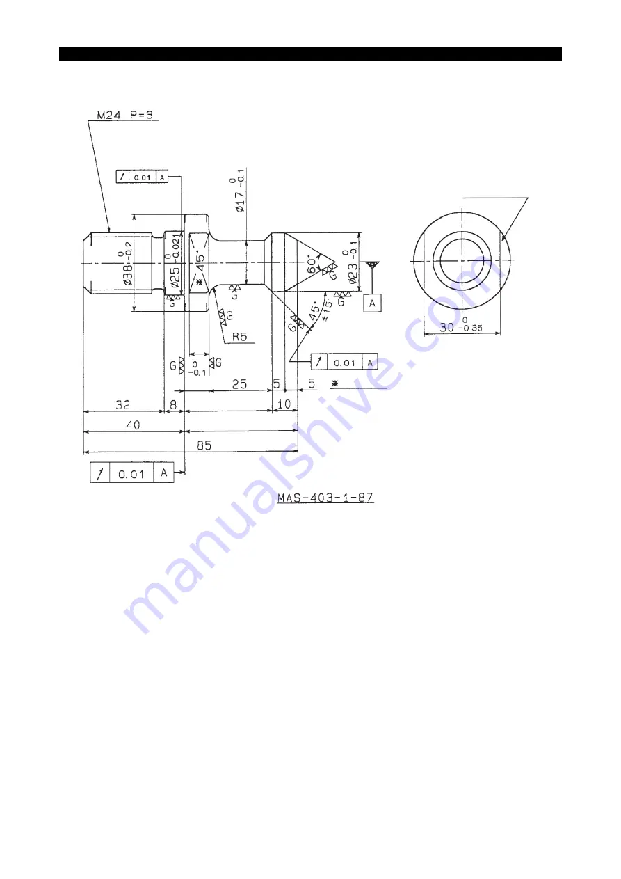
(

φ

1.50         )

0

0.008

(

φ

0.98          )

 0

-0.008

(

φ

0.67          )

 0

-0.004

(

φ

0.91          )

 0

-0.004

(1.18          )

 0
-0.004

Stamp "45

°

"

 (1.26)

 (1.57)

(0.31)

35       (1.38          )

8

(0.31)

0
-0.1

 0
-0.004

10 (0.39          )

 0
-0.004

45       (1.77          )

0
-0.1

 0
-0.004

 (0.39)

(0.20)

(0.20)

(0.98)

(3.35)

Stamp "5"

Material           :
Heat treatment:

SNCM420
Carburizing (HRC 60 or harder)

(0.20)

Summary of Contents for VTM-200

Page 1: ...VERTICAL MULTITASKING MACHINE VTM 200 OSP P200 OPERATION MAINTENANCE 1st Edition Pub No 5699 E LE11 214 R1 Dec 2009...

Page 2: ...to Section 2 Transportation and Installation Relocation f To maintain the guaranteed accuracy you are advised to care and control the factory tem perature Prepare the primary power supply that satisfi...

Page 3: ...spindle speed and application pressure are indicated on the name plate on the front shield and on the chuck body The allowable maximum speed and the applica ble pressure ensure a chucking force that...

Page 4: ...non soluble coolant is used Change and replenish the lubricating oil and coolant in each reservoir according to the sched ules in the manual Clean the filters according to the schedules in the manual...

Page 5: ...y a Spindle rotation b Turret indexing c Axis movement Never touch chips or the workpiece while the spindle is rotating Never attempt to stop a moving object by hand or with a tool Check the jaw insta...

Page 6: ...tall fire fighting equipment such as auto extinguisher In this case inform us of your intention in the stage of examining your facility When machining flammable material a Before machining any of the...

Page 7: ...he bolts which are not used for fixing the toolholders 8 Workpiece Loading and Unloading Make sure that workpieces are loaded and unloaded securely Before loading or unloading a workpiece retract the...

Page 8: ...s dangerous as strong magnetic attraction is exposed while after disassembling the strong magnetic housing unit Disassembling work requires special knowledge and jigs 2 Danger of powerful magnet Follo...

Page 9: ...n Operation panel Slide hold button Operation panel Alarm display Operation panel Short circuit breaker Electric control cabinet optional Cycle start requiring simultaneous depression of both buttons...

Page 10: ...ning speed before designating G50 max speed limit function LE11214R0100100160002 Secure the jaw gripping depth as much as possible LE11214R0100100160003 When gripping a workpiece soft top jaws must be...

Page 11: ...e T groove LE11214R0100100160006 Never use double chucking method LE11214R0100100160007 16 Caution Plate The machine and its components are fitted with various caution plates Carefully read these plat...

Page 12: ...5699 E P xi SAFETY PRECAUTIONS 16 1 Caution Plate Positions LE11214R0100100180001...

Page 13: ...4 1110 43 8 Caution plate for getting caught in chuck and jaw H1042 1187 55 H1044 1110 44 9 Cautions for chuck H1090 1142 73 H1090 1144 66 10 Cautions on chuck replacement H1090 1100 17 H1090 1100 21...

Page 14: ...ions on ATC magazine Okuma Part No H1090 1047 91 2 LE11214R0100100190002 3 Cautions for removing the maintenance cover Okuma Part No H1090 1018 33 LE11214R0100100190003 4 Cautions for steps Okuma Part...

Page 15: ...5699 E P xiv SAFETY PRECAUTIONS 5 Caution for MG Okuma Part No H1090 1144 65 LE11214R0100100190005 6 Caution on open close of operator door Okuma Part No H1090 1018 82 1 LE11214R0100100190006...

Page 16: ...getting caught in spindle Okuma Part No H1044 1110 43 LE11214R0100100190007 8 Caution plate for getting caught in chuck and jaw Okuma Part No H1044 1110 44 LE11214R0100100190008 9 Cautions for chuck...

Page 17: ...1100 21 LE11214R0100100190010 11 Cooling oil maintenance Okuma Part No H1090 1022 32 1 LE11214R0100100190011 12 Tool handling locked in and fire prevention Okuma Part No H1090 1042 43 1 LE11214R010010...

Page 18: ...ting air source pressure Okuma Part No H1090 1022 33 1 LE11214R0100100190014 15 Cautions for operating spindle and ATC Okuma Part No H1090 1041 41 LE11214R0100100190015 16 Cautions on manual tool chan...

Page 19: ...ic door optional Okuma Part No H1090 1090 77 LE11214R0100100190017 18 Air pressure for ABSOSCALE optional Okuma Part No H1090 1024 66 1 LE11214R0100100190018 19 Filter maintenance for ABSOSCALE option...

Page 20: ...explains the proper handling of the machine to make the best use of its performance and the maintenance inspection to maintain the machining accuracy for a long period of time Carefully read this man...

Page 21: ...OPERATION OF CNC LATHE 11 1 Before Starting Operations 11 1 1 NC Operation 11 1 2 Setting Zero Offsets 12 2 Machine Operation 24 2 1 Axis Direction 24 2 2 Lubrication and Inspection Method 25 2 3 Spin...

Page 22: ...Belt Tension 65 9 2 Changing the V Belt 66 10 Replacing the Leaf Chain 66 10 1 Changing Method 67 11 Front Door Safety Window Glass Replacement 68 11 1 Replacement Interval 68 12 Troubleshooting 69 1...

Page 23: ...indle nose to floor Work spindle Spindle nose 380 14 96 flat Diameter of spindle front part mm in 260 10 24 Spindle tapered bore mm in 164 6 46 2 Thru spindle hole diameter mm in 160 6 30 Spindle supp...

Page 24: ...250 9 84 Max tool weight kg lb 30 66 Standard tool mm in 25 1 32 1 1 4 Boring bar diameter mm in 40 1 3 4 50 2 M spindle front diameter mm in 90 3 54 Number of M spindle speeds Variable High low outp...

Page 25: ...r kW hp AC 0 017 0 02 2P Coolant motor 50 60Hz Turret kW hp Side thru spindle AC 0 37 0 49 0 55 0 73 2P Turret front and rear kW hp AC 0 37 0 49 0 55 0 73 2P For cleaning kW hp AC 0 37 0 49 0 55 0 73...

Page 26: ...NC control box Spindle lubrication unit 669 26 34 781 30 75 2000 78 74 2107 82 95 3859 151 93 800 31 50 1498 5 59 00 1498 5 59 00 1498 5 59 00 525 20 67 525 20 67 525 20 67 1200 47 24 Hydraulic unit...

Page 27: ...TION REQUIREMENTS for reference The installation site should be kept as far as possible from vibration sources such as roads stamping press type equipment or planer type machine tools If nearby source...

Page 28: ...and estimated bearing capacity Machine mass machine body 36 tool magazine Max workpiece mass table workpiece Foundation concrete mass Average bearing capacity of soil under foundation concrete Require...

Page 29: ...A 60 mm2 230 V 175 A 60 mm2 380 V 100 A 30 mm2 400 V 100 A 30 mm2 415 V 100 A 30 mm2 440 V 100 A 30 mm2 480 V 100 A 30 mm2 Wiring breaker See the table below Cable size See the table below Ground Mai...

Page 30: ...t may be activated 5 For further information on instantaneous power regulation and power source induc tance please inquire at your Okuma representative 6 To furnish the power supply line in the machin...

Page 31: ...pindle motor is decelerating and take the maximum value as V1 4 Calculate the momentary voltage fluctuation ratio using the formula shown below Momentary voltage fluctuation ratio V1 V0 V0 100 Note 1...

Page 32: ...nce For oils to be supplied to an optional kit check with us separately Power Supply Unit Power Source Inductance MPS10 Max 400 H MPS20 Max 140 H MPS30 Max 140 H MPS45A Max 70 H MPS60 Max 70 H 1 If mo...

Page 33: ...ual CAUTION 1 1 NC Operation Before you begin to operate the machine automatically by tape make it a rule to check the following points against a process sheet a program manuscript or any other chart...

Page 34: ...am zero on the Z axis will vary depending on the setup incl chuck jaws etc as indicated with A and B in the figure below LE11214R0100500040001 The operator can establish the reference point for machin...

Page 35: ...Actual position Tool with tool offsets Current position ZA on machine coordinate system Current position ZA on machine coordinate system The control always performs calculation ZA Z0 to obtain the ac...

Page 36: ...e modified Explanation for each case is provided in this paragraph with the following example LE11214R0100500060001 Case where zero offset value is unknown The explanation below is provided with 1 mm...

Page 37: ...dimensioned from the program zero by manual operation 100 000 in the example below LE11214R0100500070002 3 Select the ZERO SET mode by pressing the ZERO SET key LE11214R0100500070003 4 The display sc...

Page 38: ...th the cursor control keys move the cursor to the data column of ZERO OFFSET for Z LE11214R0100500070005 LE11214R0100500070006 6 Press the function key F3 CAL 7 Key in 1 0 0 through the keyboard LE112...

Page 39: ...OF CNC LATHE LE11214R0100500070008 8 Press the WRITE key With this the coordinate system is established so that the present tool position takes coordi nate value Z100 mm 3 94 in LE11214R0100500070009...

Page 40: ...irection until zero offset setting is completed Keep locating the turret in the position set in the step 1 For the X axis the reference point does not change even when the checking method or setup cha...

Page 41: ...and 2 as explained before 2 Enter tool offset data to tool offset 1 register Refer to Setting Tool Offset in Data Operation of OSP Operation Manual 3 Cut the end face of the part by moving only the X...

Page 42: ...ocedure 1 Select the ZERO SET mode by pressing the ZERO SET key LE11214R0100500080001 2 The display screen is as shown below LE11214R0100500080002 3 With the cursor control keys move the cursor to the...

Page 43: ...RATION OF CNC LATHE 6 Press the WRITE key LE11214R0100500080004 With the steps indicated above keyed in zero offset value is stored in the zero offset area of the memory For Z axis zero offset entry t...

Page 44: ...0 000 Procedure 1 Select the ZERO SET mode by pressing the ZERO SET key LE11214R0100500090001 2 With the cursor control keys move the cursor to the data column ZERO OFFSET for X 3 Press the function k...

Page 45: ...isplay screen changes as shown below With the WRITE key pressed the following calculation is performed in the control and the result is stored as the X axis zero offset value 450 230 10 000 440 230 LE...

Page 46: ...ration 2 1 Axis Direction LE11214R0100500100001 Axis movements and directions Travel Positive direction X axis Lateral movement perpendicular to the headstock To the right Z axis Vertical movement alo...

Page 47: ...n per month Once every 4 months for 500 hors of operation per month Set pressure 60 MPa 8 706 psi 1 For detailed operation procedures refer to the appended instruction manual for the hydraulic power u...

Page 48: ...g is performed within a con stant output range High speed and low speed of spindle speed are selected by coil switching LE11214R0100500120002 min 1 Spindle speed kW Output Nm Torque 300 42 22 kW 30 hp...

Page 49: ...put range High speed and low speed of spindle speed are selected by coil switching LE11214R0100500130002 min 1 Spindle speed kW Output Nm Torque 1100 72 Nm 53 1 lbf ft 15 min 53 Nm 39 1 lbf ft cont 20...

Page 50: ...C axis indexing rapid feed Brake free Cutting while controlling C axis profile generation etc Brake pressure 2 MPa 290 psi Cutting while clamping C axis drilling tapping keyway cutting etc Brake pres...

Page 51: ...ction 3 Tool Shank Pull stud Dimensions If a tool having a wrong dimension is used the NC may detect the error no tool in spindle or incomplete clamp ing disabling spindle rotation 4 Max tool length 5...

Page 52: ...to the dimensions specified in MAS 403 1982 BT50 2 For the pull stud shape refer to the dimensions specified in MAS 403 1982 P50 Type 2 1 394 1 394 1 18 1 012 No 50 Taper 7 24 0 20 0 20 0 31 0 31 0 2...

Page 53: ...ed in MAS 403 1982 BT50 2 For the pull stud shape refer to the dimensions specified in MAS 403 1982 P50 Type 1 0 20 0 020 0 0 4 1 394 1 394 1 18 1 012 NT No 50 Taper 7 24 0 20 0 20 0 31 10 0 39 11 0 3...

Page 54: ...7 21 25 31 31 M12 M12 M16 M20 M24 M30 M30 24 24 30 38 45 56 56 34 34 43 53 62 76 76 20 22 25 30 35 40 45 46 53 63 85 100 120 155 38 43 53 73 85 107 135 13 6 14 6 16 6 21 2 23 2 26 2 28 2 17 633 21 650...

Page 55: ...0 62500 3 835 0 15098 9 195 0 36201 98 43 3 8752 91 29 3 5941 69 85 2 7500 60 69 85 2 7500 34 925 1 37500 38 1 50 17 0 67 23 0 91 6 0 6 0 128 57 5 0618 69 85 2 7500 25 4 1 000 11 02 0 4339 1 48 0 058...

Page 56: ...1214R0100500190001 1 50 0 0 008 0 98 0 0 008 0 67 0 0 004 0 91 0 0 004 1 18 0 0 004 Stamp 60 1 26 1 57 0 31 35 1 38 0 0 1 0 0 004 10 0 39 0 0 004 45 1 77 0 0 1 0 0 004 0 39 0 20 0 20 0 98 8 0 31 3 35...

Page 57: ...00190002 1 50 0 0 008 0 98 0 0 008 0 67 0 0 004 0 91 0 0 004 1 18 0 0 004 Stamp 45 1 26 1 57 0 31 35 1 38 8 0 31 0 0 1 0 0 004 10 0 39 0 0 004 45 1 77 0 0 1 0 0 004 0 39 0 20 0 20 0 98 3 35 Stamp 5 Ma...

Page 58: ...rotary joint at the spindle upper part as a device for discharging coolant Broken or clogged coolant filters may cause damage to this rotary joint Clean the filters and change the filter elements peri...

Page 59: ...can be stores in the magazine with the adjacent pots occupied with tools LE11214R0100500220001 Maximum Tool Size without Adjacent Tools The maximum tool dimensions that can be stores in the magazine...

Page 60: ...ax tool weight moment 60 N m 44 lbf ft Maximum tool weight The maximum tool weight including a shank 30 kg 66 lb Maximum tool weight moment Maximum tool weight moment 60 N m 44 lbf ft LE11214R01005002...

Page 61: ...well considering the weight balance Note LE11214R0100500250001 As for Okuma OD turning or end face tool holders mill holder size that is free of interfer ence with adjacent tools is 120 mm 4 72 in or...

Page 62: ...te them well considering the weight balance Note LE11214R0100500260001 If storing an Okuma turning tool holder store milling holders of 120 4 72 or less in the adjacent pots to avoid interference Do n...

Page 63: ...d as accessories 5 When storing a tool in the magazine clean the taper shank 6 When storing a tool in the tool pot of the specified number strongly push the tool into the pot The tool will be held by...

Page 64: ...5699 E P 42 SECTION 3 OPERATION OF CNC LATHE Diagram LE11214R0100500280001 37 16 24 18 22 23 32 9 10 31 17 21 19 20 26 15 27 13 12 29 35 6 4 36 30 14 7 5 11 28 34 1 25 33 8 39 2 38 3...

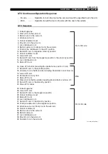
Page 65: ...y position 14 Lock middle arm pot 15 Raise ATC arm 16 Open ATC shutter including M spindle home position 1 lock 17 Send ATC arm to the spindle position 18 Unclamp tool in the M spindle including M spi...

Page 66: ...ot 2 When indexing the magazine manually close the magazine door and ensure that maga zine indexing does not cause problems 3 Check that the tool pull stud is of the proper dimensions 4 When the tool...

Page 67: ...9 min 1 for lathe spindle 50 min 1 for milling spindle b Max feedrate 2 m min 7 fpm c The turret can be indexed only when it is indexed station by station in manual mode the other mode is not allowed...

Page 68: ...t it comes to a complete stop The spindle might be rotat ing due to inertia When you unlock the door during machine operation the machine is stopped by inter lock function Do not unlock the door lock...

Page 69: ...the CONTROL OFF button on the operation panel 2 Turn the main switch on the control box to OFF 3 Clean the machine and keep the surrounding area neat and in order 2 8 Manually Operated Chuck Inspectio...

Page 70: ...Air panel 3 Check air source pressure 0 5 MPa 72 55 psi Air panel 4 Check and replenish the coolant oil tank Coolant tank 5 Clean the spindle tapered bore Milling spindle 6 Remove chips and clean In t...

Page 71: ...aning the Safety Window 1 Use a soft cloth for cleaning Do not use a scourer or hard cloth 2 Use water or warm water when removing dirt If it is difficult to remove dirt use a neutral deter gent for e...

Page 72: ...f such coolant 3 To maintain the coolant oil performance and the filter performance life for a long time you should know the correct maintenance methods such as how to dilute the coolant with water an...

Page 73: ...il Shell Tonna Oil S68 Oils other than the recommended one may deteriorate accuracy Coolant type may vary depending on materials and tools Consult your local dealer 1000 1100 Drum filter conveyor Lift...

Page 74: ...rmometer Oil Filter Clean or Change filter element Check condition of filter element Flow Sight Check oil flow by visual inspection through window gear rotary ring or spout devices Oil Pump Operate ma...

Page 75: ...d thus be made from them Because slideway lubricating oil contains additives such as extreme pressure additive it could incur variety of troubles if reacting with other oils or coolant Therefore pay s...

Page 76: ...ade more fre quently than specified in the above table All the spindle bearings are lubricated by packed high quality grease requiring no further greasing Oil Specification ISO CKB32 Amount 19 L 5 0 g...

Page 77: ...iter 1 59 gal Effective amount 3 6 liter 0 95 gal Oil Change Interval Replenish as required Low lubrication level alarm detected by the level switch occurs in approx 70 hour operation Check oil level...

Page 78: ...ure When no lubricating oil is delivered Oil level is low Replenish the lubricating oil of the same brand The pump is at a rest The pump operates intermittently The pump operation interval is set at a...

Page 79: ...and milling spindle body to optimum values in synchronization with the machine body temperature LE11214R0100600120001 4 1 Lubrication Specified Oil ISO FC2 Amount 50 L 13 21 gal Oil Change Interval I...

Page 80: ...ping it toward you 2 Clean the filter once in two weeks 3 To clean the filter wash it with water or use compressed air CAUTION 1 Negligence of periodical cleaning of the air filter will decrease the c...

Page 81: ...rection 2 Draining Oil from the Air Filter a Air filter The air filter removes moisture from the supplied air to prevent corrosion inside the machine The supplied air temperature should be is within t...

Page 82: ...ing regulator set pressure Set pressure 0 03 MPa Adjusting method Lightly pull down the pressure adjusting knob To increase the pressure turn the knob clockwise To decrease the pressure turn the knob...

Page 83: ...he instructions below X axis wiper Procedure 1 Turn on the power NFB CNC Operation Preparation in that order 2 Move the Z axis turret close to the positive stroke end 3 Turn off the power CNC NFB in t...

Page 84: ...ideway Tapered Gibs The tapered gibs are mounted on each slideways to keep the optimized clearance on the slideways If the condition changes from using the machine for a long period of time make the f...

Page 85: ...s has proper load value as specified in the chart below press the pushbutton to feed the turret If the load value is considerably off adjust the screws until you obtain the proper value Axis Tightenin...

Page 86: ...ng val ues can be obtained Adjustment of V belt tension is important for maintaining accuracy CAUTION LE11214R0100600200001 The V belts are worn once they are slipped and therefore be sure to check th...

Page 87: ...r the belt is slack gradually tighten the adjusting bolt to take up the slack of belt Mark up a point to where slackness is run out 5 Start tightening the adjusting bolt again Tighten the fixing bolt...

Page 88: ...n Leaf chain extends because of wear of pin or bush Check the chain extension in the periodical inspection every six months and if the measured dimension is over the allowable dimension change the lea...

Page 89: ...ff 6 Remove the leaf chain to replace it with the new one 7 The installation procedure is the reverse of the removal procedure step 1 to 5 How to Remove the Leaf Chain Pull out the split pin indicated...

Page 90: ...ty Window Glass Replacement 11 1 Replacement Interval WARNING Safety window glass performance gradually deteriorates due to coolant corrosion Accordingly scattering chips and workpiece may fly out bre...

Page 91: ...tion unit See Adjusting Centralized Lubrication Unit in this section Step3 3 Distrubution valve is not operating Change the centralized lubrica tion unit STEP CASE YES NO 1 Coolant pump motor is not r...

Page 92: ...5 80 4 Regulator SMC AR20 02BG 1 M spindle headstock F0015 410 001 43 5 Gap sensor ASAHI 616JX2 LDC N 1 M spindle headstock T019 400 010 10 6 Speed controller SMC AS3211F 03 06S 2 M spindle headstock...

Page 93: ...7 52 1 M spindle headstock F0001 431 001 09 6 Base block NACHI MOB 01Y W2 10 1 M spindle headstock H0039 0003 35 7 Pressure gauge w glycerin ASK OPG DT R1 4 39x10MPa 1 M spindle headstock T019 400 00...

Page 94: ...253 15 Limit switch Omron D4E 1A10N 2 ATC shutter open close confir mation E3019 397 253 16 Fluorescent lamp Nikki AW536DBG AW560 36W cable 2M 1 Work lamp on MG side E3534 905 001 17 Fluorescent lamp...

Page 95: ...Plate Okuma Nitrile rubber 452 5X815X10 3 Door H1020 1253 78 21 Suction filter Kamui KNF 06 1 1 Coolant tank H0032 0003 66 22 Line filter Masuda Manufacturing F HLME04 20S04T 1 100P 2 1 Coolant tank...

Page 96: ...1 26 sq Copying 25 0 98 sq 32 1 26 sq Drills OD face finishing 32 1 26 sq 25 0 98 sq Miscellaneous rotary tools OD face rough cutting 25 0 98 sq OD face finishing 25 0 98 sq Copying 25 0 98 sq Boring...

Page 97: ...ensions LE11214R0100800020001 Detail of A 15 M24 Depth 50 1 97 6 M8 Depth 25 0 98 Chuck mounting surface 12 M12 Depth 25 0 98 Taper 2 540 21 26 480 18 90 14 96 9 45 6 46 1 3752 Taper 2 6 30 6 46 8 07...

Page 98: ...8457 11 42 0 4496 Gauge line NST No 50 100 3 94 85 3 35 136 8 0 2 5 386 0 008 10 0 39 35 0 0 1 69 85 2 7500 45 1 77 101 8 0 2 4 008 0 008 186 3 7 335 3 0 12 36 5 1 437 38 1 50 1 5 0 059 Tool shank dim...

Page 99: ...erage tool weight inside the magazine 20 kg 44 lb Maximum tool size w adjacent tools Maximum tool space when the tool is used with adjacent tools Maximum tool size w o adjacent tools Maximum tool spac...

Page 100: ...0 0 79 A B C D 195 7 68 165 6 50 75 2 95 120 4 72 105 4 13 60 2 36 D 55 2 17 A C C 75 2 95 75 2 95 150 5 91 B 45 5 1 791 23 0 91 35 5 1 398 20 0 79 C D 32 1 26 25 0 98 B 64 2 52 50 1 97 A HF20 32 HF20...

Page 101: ...95 60 2 36 75 2 95 165 6 50 75 2 95 60 2 36 75 2 95 75 2 95 150 5 91 75 2 95 75 2 95 150 5 91 A B C C 30 1 18 40 1 57 A 20 0 79 55 2 17 2 coolant hole PT 1 4 coolant hole Hole depth 110 4 33 4 M12 HB...

Page 102: ...D toolholder HB20 25S LE11214R0100800060002 Unit mm in 110 4 33 Table top Spindle end 1490 58 66 210 8 27 210 8 27 150 5 91 max 50 1 97 50 50 1 97 1 97 50 1 97 1150 45 28 1200 47 24 360 14 17 Unit mm...

Page 103: ...060004 Unit mm in 161 6 34 2000 78 74 1400 55 12 1000 39 37 325 12 80 1600 62 99 Spindle end 165 6 50 275 10 83 160 6 30 896 35 28 1200 47 24 304 11 97 150 5 91 1350 53 15 Unit mm in 161 6 34 240 9 45...

Page 104: ...33 90 339 13 35 115 4 53 2000 78 74 1000 39 37 375 14 76 375 14 76 1600 62 99 115 4 53 Spindle end 225 8 86 225 8 86 375 14 76 225 8 86 1400 55 12 Unit mm in 110 4 33 244 9 61 816 32 13 384 15 12 70 2...

Page 105: ...ON 6 APPENDED DIAGRAMS 7 Hydraulic Circuit Diagrams LE11214R0100800070001 to Magazine Half clamp OP Turns OFF 13 L or below Full clamp Tool unclamp M spindle lock Turns OFF below 3 Mpa due to L spindl...

Page 106: ...pindle lock 4 Reducing valve reducing valve TGMX2 3 PP BW G 50J Tokyo Keiki 1 F0011 730 000 13 M spindle lock 5 S Solenoid valve DG4V 3 2A M U7 H 7 52 Tokyo Keiki 1 F0001 431 001 09 Tool unclamp 6 Bas...

Page 107: ...shutter ATS sensor arm advance retract OP ATS sensor cover up down OP Door lock during rotation OP Slide door OP ATS air blow OP MG side cover Tool tip coolant M spindle head Air gun ATCMG unit OFF s...

Page 108: ...eated confirmation 5 Gap sensor 616JX2 LDC N ASAHI 1 T019 400 010 10 Lathe boulder seated confirmation 6 Speed controller AS3211F 03 06S SMC 2 F0031 582 000 51 Purge air 7 In line check valve 2232B 3S...

Page 109: ...nual may be at variance with the actual product due to specification or design changes Please also note that specifications are subject to change without notice If you require clarification or further...

Reviews: