


5699-E P-32
SECTION 3 OPERATION (OF CNC LATHE)
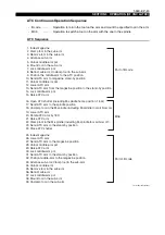
Tool Shank Dimensions
LE11214R0100500170001
[Supplement]
Note
* The 7/24 taper angle tolerance is based on +AT4/-0 JIS B 0614 taper angle tolerance
ranked AT4.
1) The tolerance shall be the middle class specified in JIS B0405 unless otherwise speci-
fied.
2) It is advisable to provide clearance at d
2
for finish-grinding of the reference hole.
t
b
60
d2
D1
D6
D5
D4
d1
t
4
R
d
x
e
y
1
x
v
0
30 -15
0
30 -15
Gauge line
7/24
0.02 A
0.02 A
w
A
0.05 A
A
2
3
1
5
y
1
BT30
BT35
BT40
BT45
BT50
BT55
BT60
BT30
BT35
BT40
BT45
BT50
BT55
BT60
31.75
38.10
44.45
57.15
69.85
88.90
107.95
48.4
56.4
65.4
82.8
101.8
126.8
161.8
0.5
0.5
1
1
1
1
1
14
14
19
23
27
33
33
12.5
12.5
17
21
25
31
31
M12
M12
M16
M20
M24
M30
M30
24
24
30
38
45
56
56
34
34
43
53
62
76
76
20
22
25
30
35
40
45
46
53
63
85
100
120
155
38
43
53
73
85
107
135
13.6
14.6
16.6
21.2
23.2
26.2
28.2
17.633
21.650
25.375
33.000
40.158
51.917
60.758
56.144
65.680
75.679
100.216
119.019
147.823
180.359
4
5
5
6
7
9
11
8
10
10
12
15
18
20
8
10
10
12
15
18
20
2
2
2
3
3
3
3
2
2
2
3
3
3
3
0.0039
0
0.0045
0
0.0041
0
0.0052
0
0.0051
0
0.0063
0
0.0065
0
7.0
7.0
9.0
11.0
13.0
16.0
16.0
16.1
16.1
16.1
19.3
25.7
25.7
25.7
17
20
21
26
31
31
34
16.3
19.6
22.6
29.1
35.4
45.1
60.1
0.12
0.12
0.12
0.12
0.2
0.2
0.2
Nominal
No.
Shank
Flange
Allowance
of
7/24 Taper *
AT
D
Reference
Smaller
end
Diameter
Thread
Slot on Flange
D
1
D
4
D
6
e
x
d
d
1
W
1
0.2
2
(Min.)
R
(Max.)
d
2
H8
D
5
h8
b
H12
6H
4
0.5
0
t
0
0.2
3
(Min.)
5
(Min.)
x
1
0.1
0
y
1
0
0.4
v
0.1
y
0.4
Unit: mm
Nominal
No.
Pull-stud data excerpted from MAS 403-1982
Table 1 Taper shank


